backyard millyard....midmount....

Hello members....

I got the rear wheel top stays tacked in.....all seems good....ie..rear wheel drop-outs sitting the same,,,motor-cage square to stays...

Recieved a gear cassette to suit style of rear wheel...now I can lay the final drive chain and check clearances on the r/h side...

There is one area of re-work that I need to attend to and that is the jackshaft mount bracket...it appears it needs to be raised 10-15mm ...no big deal..

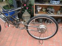
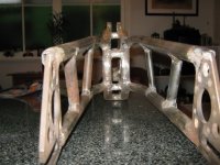
Shoud be able to tack-up shock mount nextIMG_0160 (640x480).jpg

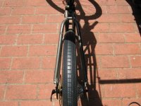
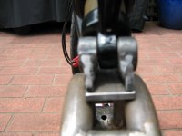
a view from the rear......IMG_0159 (640x480).jpg

a view from the front
 
Beautiful job.
 
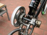
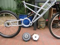
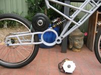
The issue with the jackshaft.....I hope that the photo shows whats happening....

I will trim the bolt...then the bearing housing( there's at least 5mm of wasted width )....

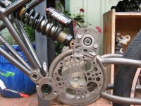
The rear end of the shock ..clashes with the gng bearing housing and bolt...last recourse raise unit 10/15mm..

I'm glad that there was only 1 inboard mount to deal with...
 
A bit of a side track to the swing-arm....

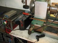
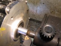
How to deal with that pesky 14 tooth motor-drive pulley....in a more controlled manner....

This is the method that I shall follow....

I will let the lathe support the job...the 48v battery pack...motor-controller and throttle will provide the motive force....

I will use the lathe toolpost to controll cutting away of pulley...to make new drive bose.....

I will use 2 scotch keys of 4/5mm to lock new pulley to drive bose....

my lathe motor is rated at 600watts....the gng motor at 500watts.....I think I'm in the ballpark for light machining.....

That's the theory.....I think that it's a sound approach.....
 
I've used a hubbie to lathe itself, and it works quite well. In your case I'd worry about the rpm, since at low rpm you don't have near the power. It's worth a try though and probably fine as long as you don't take a big bite.

John
 
hey members,,,,

Bit of an upate...since my last post I repossitioned some items...

The reason being....I could not fit a larger driven aluminium pulley....should I wish too....

Even though I had clearance it was of a minimal natrue....now was the time to adjust to get things into a final position......

So I dropped the top wheel stays down about 25mm....rolled jack-shaft mount by about 12mm....and re-tacked......

Now I can fit a larger aluminium driven gear by 25mm...on it's dia....

I want to be able to change any gear....should I wish to in the future,....and I do..IMG_0166 (640x480).jpg

The front/left elect motor mount shows new position compaired to old position...IMG_0168 (640x480).jpg

So now when i stand back and have a look....things look proportional and in the ballpark.....

All i did was reposition items so that i had the max amount of clearance at the top of motor cage......
 
Hello members,

I have managed to get the shock mount sorted out........7 pieces..

2 off luggs....drilled offset....

2 off brass bushes....same standard as manito shock....

2 off cradles...

1 off foot...

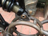
I hope pic shows things....IMG_0171 (640x480).jpg

So now I have the major swing-arm pieces in they're final places....still need to do rear brake caliper mount and derailer set-up....View attachment 1

End of the day alignments......I have a 2mm discreptancey between shock and swing-arm.....this is spring...

This spring can be dealt with by a push of my thumb......IMG_0174 (640x480).jpg .....for all practical purposes....I think I'm in the ballpark....
 
How did you go machining off the original motor pulley? Very interested here, as others have stated, its too small.
 
Hello heathyoung...

I have not machined the 14t pulley yet.....and will not untill i have an 18t in my hand...which i can get locally...rs components for Aust....

I've been more concerned with the swing-arm.....big things first then little things latter...i've still got a mountain of welding and dressing to do yet....

Give me a week or two.....and i would have dealt with this issue....
 
.Hello members....

managed to get some things fully welded so that now i can sit on the bike....bounce up and down....everything looks sweet...clearances good....

Fully welded ....rear drop-outs...rear wheel stays..,motor cage to bb tube...tacked shock-mount...

I used my 26'' hub wheel for final shock-mount position....that way things should be close to the original height of my seat position....which it is....IMG_0177 (640x480).jpg......

I've now put in the 24'' wheel....which has the gear cassette....I need to do a 26'' wheel latter.......

Now it's time to look deeper into the techincal lay-out of this kit into my swing-arm.....ie l/h and r/h drive things.....

Eg....14t sprocket changed to 18/20t...both are in the mail...maybe tomorrow???....

new drive belt....500mm..I have a taller jack-shaft centre distance than standard....hence the next size up in belt.....combined with the largest diameter belt follower/guide that i can fit in....

Large diameter pulley has the gng signature run-out....needs to be addressed.....maybe get a larger pulley and pay for two key-ways to be done at the same time.....

I then need to look at guarding....these soon to-be spinning items are close to my ankels and the cuffs of my jeans...hoping gng guarding can be used....if not i'll work out something...

and this is only the left/hand side.....
 
Nice work as always!

Totally irrelevant: this photo reminds me of the one I took earlier this month :)
tri-lobe said:
file.php
something.jpg
 
Hello members....

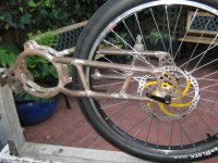
Bit of an update....I've got 95% of welds done...rear brake caliper mount outstanding..IMG_0180 (640x480).jpg

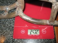
so lets see what the swingarm weighs in at....on the chinese 5kg kitchen scale......IMG_0183 (640x480).jpg

I'm happy with the weight......less than 2.5kg......and i've still got some dressing-up/grinding to do....

I put about 600gms of mig wire into this...34 welds....If i was to do this again,,,,I would reduce the welds by 12.....Hey...I am a beginner...IMG_0184 (640x480).jpg


Wheelbase has come in at 1025mm......I think that thats ok....not too long....
 
Hello members...

To compare apples with apples i weighed up 2 other swing-arms......an original huffy style and a modified one [used with hub motor]...IMG_0185 (640x480).jpg


The standard weighs in at 1800gm....

The hub motor swing-arm weighs in at 2150gms...

midmount swing-arm weighs in at 2430grms...
 
Hey members....

I was kicking back having a beer,looking at un-used space in the rear end....around where the shock lives...also the position of where the motor cage sits....

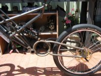
I think that one could fit a Barfang into a swing-arm.....the space is there....IMG_0188 (640x480).jpg

I would remove the lh/rh spoke flanges.....to get the smallest od.......IMG_0189 (640x480).jpg

The thickness of the hubmotor....with shaft mods to suit...appears to be in the ballpark......

With all the work being done by different members in this area of mid-drives......a suitable arrangement would be found and copied [ i hope no-one minds, i'm not doing this for comercial gain.]

what do you guys reckon????
 
edit: The MAC geared hub is has reasonably LOW eddy-current (which causes waste heat, even when unloaded) up to above 1,300-RPMs. The lower pole-count Bafang should be able to be run up to more than 2,000-RPMs while still having low eddy-currents. So, you can spin the Bafang roughly twice as fast as the MAC, and then you can externally gear it back down to the same wheel speed. This has the effect of the Bafang being able to perform as though it's twice as big as the MAC, in regards to max power capability and ability to put out that power while staying cool. Also, the Bafang is roughly half the price of the MAC...

I've been following crossbreaks conversion to make the axle spin, I believe it's a very important development. There are minor variations inside the geared hubs, and I was relieved to read that the MAC from cell_man not only worked, but was easier than others that were tried. The MACs not only had a low-Kv 12T on the shelf right now, but if someone wanted to use a faster winding, he already has five different Kv's (many manufacturers only have two choices of Kv).

The Bafang is available and affordable, so I was also glad to see that it "looks like" it will take well to the conversion. The Bafang has fewer poles, so it will be the model of choice for those who want to use a faster winding and then use a large external reduction to make the RPMs useable (off road?). The higher pole-count of the MACs make them smoother when using a sensorless controller.

Since the converted motor-shell would now be stationary, it opens up a whole new world of easy fat phase wire upgrades, and active cooling mods.
 
Wow, really nice work, subscribed and thanks for sharing! :D

-JD
 
Hello members,

time to deal with 14t pulley...this is the set-up that i went with...battery,controller and throttle...
i held the throttle in one hand and did the turning with my other hand...IMG_0192 (640x480).jpg

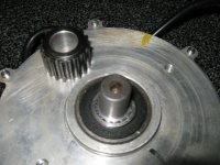
i had no problems.....20 thou/.5mm cuts.....i finnished motor shaft at 15mm dia....IMG_0195 (640x480).jpg

new 18t pulley drilled and bored to 15mm id....IMG_0196 (640x480).jpg

I still need to add 2 off 6mm grub screws as per scotch key method...
 
i've still have to deal with the run-out on the 80t gear...i can un-screw the keyed centre bose....

The plan is to sort out the 80t and a 95t at the same time...
 
Awesome work with turning down the 14T and getting an 18T on it instead. Does the 18T fit on the stock setup?
 
Hello heathyoung....

YES....the14t pulley is about 21mm dia.....so i turned it down untill i had 15mm dia...the teeth started to dissappear at about 17mm dia.....I wanted the largest dia shaft left on motor....

The 18t pulley is about 28mm dia...minus say 5mm for tooth depth....leaves 23mm to sweaze in a15mm hole with 2 off 6mm set screws/grub screws.....used as scotch keys......

With the motor connected normally....it spins anti-clockwise...perfect for normal turning.....

I had no grief whatso ever doing this mod....no crazy vibrations...probably holding throttle at 50%...

If you have access to a lathe give it a go.....

I purchased steel pulleys because...if one tries to drill a aluminium pulley onto a steel shaft...as per scotch-key method.....the drill will wander into the ally pulley more than the steel shaft...one ends up with a crap hole.......so steel pulley scotch-keyed onto steel shaft.....

I hope that the above helps.....
 
Back
Top