geofft said:
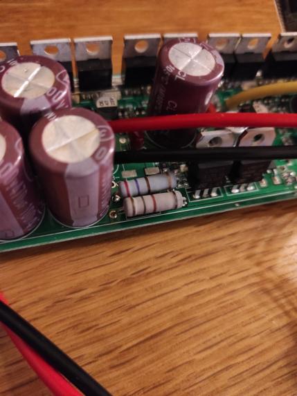
I'm having a lot of issues with a 60V+ 18fet controller, and many users here had the same issues with 18fets : resistors + LM getting VERY hot that it needs to be replaced by a DC/DC buck, controller not powering up due to wrong volt cal (the wiki is wrong for this part, as I said above).
I've read the wiki 10times if no more, and still, I burned couple of fets and I'm not the only one and trust me, I've followed EVERY step of the programming process.
Even with the 6-fet version the resistor and LM317 get pretty hot, I'm currently using the method I posted back on page 126 of this thread which has proved to be reliable. Not sure if this kind of setup would work with the 12 and 18 fet units however, I've only ever used the 6 fet.
Be careful using buck convertors to provide these internal supplies, I experimented with these (admittedly cheapo chinese types) some time ago and like yourself was getting random mosfet fails. Eventually went back to the stock setup (with the mods as above) and all has been ok since. I think the 15v line needs to be very stable and reliable, I guess the buck o/p just isn't good enough, maybe some experimentation with other high quality dc-dc supplies is needed,
I myself am running four 18 fet KT controllers (two at 52v, two at 72v) with this firmware and could not be happier! First of all, again many thanks to Stancecoke, Casainho and Xnyle for this amazing work. I can't thank you enough; you are heroes.
Now here are some insights that I had to learn to get these controllers to work at high voltages and power levels:
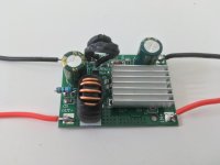
- I advice to always replace the 15V line (resistor + LM317) with a buck converter. Both for the 48V as well as the 72V version of the 18 fet Kt controller. Not only can you eliminate the scary temperatures of the resistor and LM317, but equally important I have found that at lower battery voltage levels and high power usage (but critically ABOVE lvc voltage levels), the LM317 setup cuts out prematurely, leading to an effect that resembles LVC but is not LVC. So my recommendation is to always replace the 15v line by a buck converter; this leads to much more consistent performance at lower voltage levels. I use the 120V (or 90v) -> 12V converters of Aliexpress and modify the resistors on this converter (change 12k to 15k resistors) to provide some 15,5v (the controller mosfets can take up to +/- 20v input). The 5V line on the controller is fine, you don't need to modify that part.
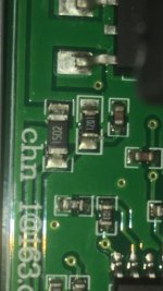
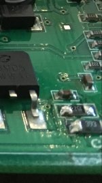
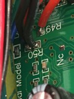
- Somehow the firmware only allows the voltage calibration factor up to a value of 100 instead of 255. So I have found that in order to make 84V (or higher) work with this firmware, you still need to modify the LVC resistor on the board even with a stock 72v controller. You need to find the set of a small and bigger smd resistors, and then replace only the bigger SMD resistor (15k or higher depending on the controller you have) by a trim resistor (30 or 50k) so that you can modify the LVC manually. Just remove the old LVC resistor from the board, solder 2 extension wires to get some working space and connect the trim resistor to the end. For a 72V controller I set the voltage calibration factor in the firmware to 89 (255*89/255=89V -> this would be the highest voltage you would ever reasonably need to be able measure when using regenerative braking, in case the BMS decides to turn off and you need the firmware to stop voltage flying to the moon) and then use the trim resistor to modify the resistance in such a way that the shown voltage in the bluosec app is the same as the voltage that you measure with a multimeter on your battery. You need to do this while the controller is turned on, so you can see the effect of what you are doing. Works like a charm, regenerative braking even with a full battery!
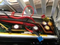
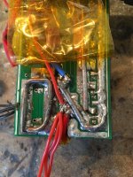
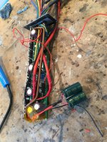
- These controllers are very versatile. This amazing firmware makes them the best controllers available for an ebike; I like them more than the sabvoton + CAv3 combination. I have modified 48V 18 fet kt controllers to 72v (other caps, mosfets, lvc) and also bought stock 72v versions. I have heavily improved the traces with lots of solder and additional thick wires + lots of 100V 1000 uF caps. Now I run these 18 fet controllers at 300 phase amps and 100 battery amps, so at 72v - 84v that is some 7000 - 8000 watts flowing through these bad boys. Not bad for such a cheap controller, and even with torque sensor functionality!! They can handle the bigger motors as well: 50mm magnets, 3T, 6mm2 phase wires, ferrofluid. All run fine!
The bluosec app from Xnyle is a piece of art in itself. It has everything one could ever whish for! I have multiple x4 connectors on my bike, so I can switch from torque sensor mode to motor temperature reading by switching to another connector. Amazing functionality!