• Howdy! we're looking for donations to finish custom knowledgebase software for this forum. Please see our Funding drive thread

TSDZ2 mid drive with 860C, 850C or SW102 displays only -- Flexible OpenSource firmware (Casainho code only)

agphil said:
I'm trying to compile the 850C display firmware with Eclipse under Windows 10, and it cannot find the header files located in the 860C_850C\src folder when compiling the common files, I get the following error:

In file included from ../../common/src/fault.c:1:
../../common/include/screen.h:8:10: fatal error: main.h: No such file or directory
8 | #include "main.h"

If I make a copy "main.h" in the folder common\include, it works but the same thing happens for all the header files.
I tried everything and cannot find a solution

@casainho or other, any ideas what I'm missing?

The makefile for windows should be corrected to include current directory, add -I. directive for the compiler and linker
 
r0mko said:
casainho said:
Yes, I would like to be able to fine tune this value on the display but was not a priority. Did you try a lower value like 7 or 6? Going in that direction the motor will start to brake, so, less torque for the same current.

For adding this feature to fine tune, it is also need documentation to explain the user how to do it and how to test/validate - how did you do it?
First I tried 5 and got very substantial increase of low-end torque, but very weak assist at high RPM. I decided to go further and set value to 0, but got very high current and weak assist at any RPM. The sound of the motor has also changed, it became louder. Then I set it to 7, this value gave a nice push at low end but virtually no assist over 560 ERPS, so I decided to stick to 8, which appears to be a sweet spot for a 36V motor at 48V and experimental high-cadence setting for motor type. The only validation and testing equipment was the motor current display vs. subjective perceptions, so you decide whether or not to consider this as a solid evidence.
I think the correct value is the one that gives the highest torque at motor low RPM. At motor RPM of 4000 (for 48V battery and 48V motor, the motor current / torque should be zero!! So, I think your correct value is 7.

What we need to implement is the field weakening and as you explain, in your case we need to start with value 7 and at some point we need to increase the value that value... we need to understand how to implement all this and then we will have the highest torque / efficiency possible in the full range!!

r0mko said:
My thoughts were the following. The PWM ramp step is 64µs, so with step of 40 the full range sweep from 0 to 255 for PWM takes 0,65 seconds. Since an average PWM ramp up during startup is about 0->60% (0-155), the value of 40 has no influence on motor responsivity, but helps to back off the motor when a sudden drop of load occurs (switching a gear, for instance).
On the display, the user can configure the motor current ramp up to 30 amps/second while the default value is 8 amps/second. Since you decreased the motor reaction time, I think you must validate that use can still configure a value up to 30 because maybe now the max value is only 20. I did various experiments but I don't know how to measure or calculate this.

About measuring the efficiency, I put my bicycle on a bike trainer and setup max load possible, then I put a fixed duty-cycle and changed that angle until get the max speed and lower battery current.
I think most users don't have the bike trainer... so maybe just looking to the display and see the lowest current.
 
Calibrated my torque sensor today using luggage scales and my body weight as the maximum weight value. Power delivery is now smooth on all assistance levels. I still use the r0mko torque only variation on this bike but I have just purchased another 36v tsdz2 for my mountain bike and will try the standard Casainho code on the mountain bike, it has gears.
 
casainho said:
hetm4n said:
Casainho Stopping the engine after stopping pedaling is probably identical, I can not distinguish it.

Here is a new version for you test, I did slower the time for the motor to stop:
https://github.com/OpenSource-EBike-firmware/TSDZ2-Smart-EBike/tree/master/releases/0.57.3

I checked 0.57.3 on the forest route under the house and it works properly, the bumps engine does not stop. On Wednesday I will go through a rocky trail with small hills for work, I will be able to test the operation more.
 
@Casainho I have discovered several small issues. Where do you prefer to report them. Here in the forum or in the GitHub?
 
plpetrov said:
@Casainho I have discovered several small issues. Where do you prefer to report them. Here in the forum or in the GitHub?
On github to be be forgotten but you can also share here your findings.
 
casainho said:
I think the correct value is the one that gives the highest torque at motor low RPM. At motor RPM of 4000 (for 48V battery and 48V motor, the motor current / torque should be zero!! So, I think your correct value is 7.

Yesterday I gave it a try with rotor offset value of 7. With this value the assist behaves fine and consistent throughout the cadence range, but my battery depleted very fast and the motor became crazy hot in no time at high RPM (80-83 RPM cadence). I even caught a complete shutdown at 85° after a steep hill. This is quite strange because I haven't seen high motor and battery current at this RPM.
 
r0mko said:
casainho said:
I think the correct value is the one that gives the highest torque at motor low RPM. At motor RPM of 4000 (for 48V battery and 48V motor, the motor current / torque should be zero!! So, I think your correct value is 7.

Yesterday I gave it a try with rotor offset value of 7. With this value the assist behaves fine and consistent throughout the cadence range, but my battery depleted very fast and the motor became crazy hot in no time at high RPM (80-83 RPM cadence). I even caught a complete shutdown at 85° after a steep hill. This is quite strange because I haven't seen high motor and battery current at this RPM.
Ok, interesting. The current value on the firmware is 10, how a small difference from 10 to 7 makes so much difference in the results. For now I would leave at 10, I don't think it is a priority as this value may be mostly the good one.


hetm4n said:
casainho said:
hetm4n said:
Casainho Stopping the engine after stopping pedaling is probably identical, I can not distinguish it.
Here is a new version for you test, I did slower the time for the motor to stop:
https://github.com/OpenSource-EBike-firmware/TSDZ2-Smart-EBike/tree/master/releases/0.57.3
I checked 0.57.3 on the forest route under the house and it works properly, the bumps engine does not stop. On Wednesday I will go through a rocky trail with small hills for work, I will be able to test the operation more.
Good. Let's see if we have a solution for both different type of bicycles / usage.
 
Today was a happy day.
TLDR: Flashed display and motor, happy!!!

Long story:
Shopping list:
48v version TSDZ2 from pswpower.com

48V 14Ah 672Wh eBike Rear Rack Battery 36V 17.5Ah 630Wh Samsung 35E Cell Electric Bicycle Batteries For 1000W 500W 250W Motor: https://www.aliexpress.com/item/33023622289.html

ST-Link V2 stlink mini STM8STM32 STLINK simulator download programming With Cover:https://www.aliexpress.com/item/2022854051.html

(850C display: Electric Bike TFT Display DPC18 850C 500C SW102 C965 C961 750C Bluetooth for BAFANG BBS Mid Drive Motor Bicycle ebike Computer: https://www.aliexpress.com/item/32857206665.html

CP2102 USB to TTL Board V3.0 Burner with Download cable Support Windows 8/7/Vista/Server 2003/XP etc with DuPont wire: https://www.aliexpress.com/item/32288431622.html

XL6009 DC Adjustable Step up boost Power Converter Module Replace LM2577
4.9: https://www.aliexpress.com/item/32807600304.html

Electric Bicycle 110CM 6PIN VLCD5 XH-18 LCD6 Display TSDZ2 Speed sensor Extension Cable For TSDZ2 Mid Drive: https://www.aliexpress.com/item/4000295965214.html

Extension Cable For Bafang MALE to MALE Center Motor/Mid Drive Motor Kit Display Three Types Display Extension Cable:
https://www.aliexpress.com/item/32861639327.html

Bafang brake sensors: Currently no link, but these are the stock brake sensors.

Some notes from my side:
with the extra cables, i can quickly plug and play to flash new firmware on display and motor. :)
Flashing of the 850c went quick, boost converter @ 31v.
Wiring the 850C to the 8 pin controller went well.
Flashing the motor take some extra time, There are 2 different pin layout versions of the ST-link v2: https://i.imgur.com/ZmJ7Tvu.jpg And i used the 3.3v pin instead of the 5v pin. I was only able to read/write fw on 3.3v.

Now it's time to configure my settings on the display :)

Firmware used:
850C_v0.8.0-bootloader.bin
TSDZ2-v0.57.2.hex
 
SuperSl0w said:
Today was a happy day.
TLDR: Flashed display and motor, happy!!!

Long story:
Shopping list:
48v version TSDZ2 from pswpower.com

48V 14Ah 672Wh eBike Rear Rack Battery 36V 17.5Ah 630Wh Samsung 35E Cell Electric Bicycle Batteries For 1000W 500W 250W Motor: https://www.aliexpress.com/item/33023622289.html

ST-Link V2 stlink mini STM8STM32 STLINK simulator download programming With Cover:https://www.aliexpress.com/item/2022854051.html

(850C display: Electric Bike TFT Display DPC18 850C 500C SW102 C965 C961 750C Bluetooth for BAFANG BBS Mid Drive Motor Bicycle ebike Computer: https://www.aliexpress.com/item/32857206665.html

CP2102 USB to TTL Board V3.0 Burner with Download cable Support Windows 8/7/Vista/Server 2003/XP etc with DuPont wire: https://www.aliexpress.com/item/32288431622.html

XL6009 DC Adjustable Step up boost Power Converter Module Replace LM2577
4.9: https://www.aliexpress.com/item/32807600304.html

Electric Bicycle 110CM 6PIN VLCD5 XH-18 LCD6 Display TSDZ2 Speed sensor Extension Cable For TSDZ2 Mid Drive: https://www.aliexpress.com/item/4000295965214.html

Extension Cable For Bafang MALE to MALE Center Motor/Mid Drive Motor Kit Display Three Types Display Extension Cable:
https://www.aliexpress.com/item/32861639327.html

Bafang brake sensors: Currently no link, but these are the stock brake sensors.

Some notes from my side:
with the extra cables, i can quickly plug and play to flash new firmware on display and motor. :)
Flashing of the 850c went quick, boost converter @ 31v.
Wiring the 850C to the 8 pin controller went well.
Flashing the motor take some extra time, There are 2 different pin layout versions of the ST-link v2: https://i.imgur.com/ZmJ7Tvu.jpg And i used the 3.3v pin instead of the 5v pin. I was only able to read/write fw on 3.3v.

Now it's time to configure my settings on the display :)

Firmware used:
850C_v0.8.0-bootloader.bin
TSDZ2-v0.57.2.hex

Congratulations! If you want some more low-end response, give it a try: https://github.com/r0mko/TSDZ2-Smart-EBike/releases/tag/v0.57.13

This is an alternative firmware for TSDZ2 that works with v0.8.0 display firmware, but uses another algorithm to calculate current. It gives you a lot more assist at low RPM but somewhat less at higher. You can start and accelerate faster, but have to rely on yourself more at higher cadence. In my opinion, this is more natural feeling, but tastes differ. Who knows, perhaps you'll
like it as well.
 
I ordered a 36V version of the motor and plan on running it with 52V battery in high cadence mode, so I guess installing a temperature sensor is very much recommended. Does anyone have experience/information on whether LM35A or LM35C sensors also work with the OSF? I live in a place where we get negative temperatures for half a year so I want to install a sensor which is rated for -40 - 110°C range (LM35CZ). The output from those will be -400mV to 1100mV. Does the OSF work with negative voltages coming from the sensor or is it only accepting 0mV to 1000mV from the LM35D sensor version mentioned in the wiki?

I'm really excited to follow the progress of this firmware and might even start to do some contributions later on if I figure out some improvements for my use case. I'm converting a downhill bike and plan on utilizing it mostly in enduro-like riding in the forest trails around here.
 
casainho said:
silvocross said:
casainho said:
silvocross said:
I would like to have this mode on my bike but I still want to have the additional functionalities coming with the SW102 Display, is it planned to work on this feature again or shall I create my own fork for this?
I would accept a contribution pull request if you would implement emtb where the user could change the points of the curve on the display and not with fixed hardcoded values like on v0.20.
OK, I'll take a deeper look in the next days on this. Thanks
I think the user should calibrate first the torque sensor and have a correct measurement of weight on the pedals, then, the emtb curve is applied and the user will clear understand that the emtb curve will apply an increasing assist factor when the user increases the pedal weight.

Would be good to try reuse the current code, if possible, of the curve for torque sensor calibration. This code uses 8 points but maybe the emtb curve could use 16 points.

Implementing the emtb curve on top of the weight on the pedals and before the calculation of the pedal human power, will make possible to keep the 2 options of using pedal torque or pedal human power as also user disable the torque sensor or cadence sensor if one of them is failing.


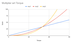
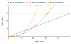
OK so I set up the dev environment and had a deeper look at the code. My proposal is to try keeping it simple and let the user just set two parameters: a multiplier and an exponential (1 to 3). This way it is possible to cover an almost infinite set of configurations, for example:

Cattura.PNG

I would then (after proper scaling and saturation) just sum this factor on top of the pedal power here (simplifyed):

Code:
current_amps = m_pedal_power * assist_level_factor + eMTBfactor*m_pedal_torque^eMTBexponential

In my opinion this solution will not require huge code changes and will be easy to be parametrized by the user. also setting a multiplier equal to 0 will automatically deactivate the function.
Would you agree on this?
 
Veko said:
.... LM35C ....The output from those will be -400mV to 1100mV. Does the OSF work with negative voltages coming from the sensor or is it only accepting 0mV to 1000mV from the LM35D sensor version mentioned in the wiki?
You’ll need to pull the output pin down to -Vs thro a resistor (50microamp/-Vs) which would mean creating-5v and then finding out whether the ADC will accept -ve voltages. That’s a tad unlikely as the original purpose was for a throttle (and the motor doesn’t ever go in reverse .. well, not yet anyway!!)

Do you get a lot of condensation occurring in your kit operating at such low temperatures? This year has been very bad here; the lowest temp was -5C and then followed by a lot of rain.
 
silvocross said:
Code:
current_amps = m_pedal_power * assist_level_factor + eMTBfactor*m_pedal_torque^eMTBexponential

In my opinion this solution will not require huge code changes and will be easy to be parametrized by the user. also setting a multiplier equal to 0 will automatically deactivate the function.
Would you agree on this?
1. I would like to better understand. I never tested the emtb on V0.20 and I assume that function come from there. Do you agree with that function, did you thought on others?

2. Can you describe what are you looking for on emtb? what issue does it solve for you?

3. When the system need to work with torque sensor or cadence sensor disabled, how do you recommend to do it, which changes to that function?
 
casainho said:
1. I would like to better understand. I never tested the emtb on V0.20 and I assume that function come from there. Do you agree with that function, did you thought on others?

2. Can you describe what are you looking for on emtb? what issue does it solve for you?

3. When the system need to work with torque sensor or cadence sensor disabled, how do you recommend to do it, which changes to that function?

1. The function in V0.20 is working OK, but assist levels are hardcoded. I propose a similar outcome with a function easier to be configured by the user.
My approach would consist on defining an assist level which is proportional (or more than proportional) to the torque applied to the pedals.

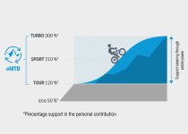
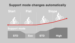
2. eMTB mode is supposed to automatically increase the assist factor during uphill or high-load sections. This limits the need to play and constantly adapting the assist levels during offroad riding. It works very well and is used in all comemrcial systems, see as an example Bosch and Yamaha below:

csm_Bosch-eBike-eMTB-Mode-Chart_EN_3c9a2251d4.jpg
pw-x2_pict_002.png

3. If the torque sensor is disabled (m_pedal_torque=0), there will be no additional assist.
If the cadence sensor is disabled, the system will still provide additional assist (depends only on the pedal torque and not on pedal power)
 
Veko said:
I ordered a 36V version of the motor and plan on running it with 52V battery in high cadence mode, so I guess installing a temperature sensor is very much recommended. Does anyone have experience/information on whether LM35A or LM35C sensors also work with the OSF? I live in a place where we get negative temperatures for half a year so I want to install a sensor which is rated for -40 - 110°C range (LM35CZ). The output from those will be -400mV to 1100mV. Does the OSF work with negative voltages coming from the sensor or is it only accepting 0mV to 1000mV from the LM35D sensor version mentioned in the wiki?

I'm really excited to follow the progress of this firmware and might even start to do some contributions later on if I figure out some improvements for my use case. I'm converting a downhill bike and plan on utilizing it mostly in enduro-like riding in the forest trails around here.

It will not work with negative voltages. More than that, you would need a negative power supply with your sensor, to bias a pull down resistor. Not really worth a pain. The purpose of the temperature sensor is a thermal shutdown and power limiting when motor gets really hot, so nobody cares about negative temperatures.
 
casainho said:
plpetrov said:
@Casainho I have discovered several small issues. Where do you prefer to report them. Here in the forum or in the GitHub?
On github to be be forgotten but you can also share here your findings.
@Casainho
I spent some time testing the newest version that gave me trouble with the "e: 8 Comms" error. While doing that, I came across some facts that can not be explained by influence from the high currents from the power cables or missing communication for a predefined period of time.

1. The error "e: 8 Comms" can not be cleared by turning the system on and off. It behaves like its value is saved somewhere in a non-volatile memory perhaps at turning off the display. One way to clear the error, that can be reproduced in 100 % of the tests, is to change the asset level and then to turn off and on the system. Another approach is display settings reset.

2. You said that the error is provoked due to noise in the TTL serial line due to high currents. While this can explain one of ten occurrences, the other nine will follow the following scenario:
- test of the motor running with asset level higher than 10.
- wait the motor to fully stop + another 5 seconds.
- change of the asset level.
This will make the error appears in every second to third repetition of the scenario. At the moment of change there is 0 motor current so I assume no interference. The error appears almost instantly.
I tried to check the code but I could not find again how this error is handled. Is the only condition that will invoke it is a communication brake for a predefined period of time as you said. What I have experienced is a bit different.
You said you had similar problem with the smaller display. Does the protocol in addition to the CRC checks has any additions to help the operation in a nosy environment, e.g. retransmissions, error corrections, etc... Having something that resembles a packet loss measured like in the ping implementation in the TCP/IP protocol might be usefull.

3. Inconsistent motor torque at the same power level. This is not something new but I never reported that, as it is not easy to reproduce. So while changing the assist levels e.g. for asset level 13, I have experienced two completely different motor responses.
- the first from which I have always complaining. With the motor power burst at the place where we read the maximum of the torque sensor.
- the second is the one it should be. Very smooth and powerful response without any peaks caused by the max values of the torque sensor. I do not know what is happening but if we can reproduce this error forever this will be my favourite motor assist calculation algorithm.
The entry and exit conditions could not be identified for the moment. What is for sure, that if I enter the second scenario, power off and on does not clear it. Also changing the asset level up and down. However after many changes of the asset level we may go back to the first.

4. I saw in your code that there is an error related to the handbrake. I tried switching on the display with the brake applied. There was no error shown in the display no mater how long I waited. However the system will start only after I release the brake. Again nothing shown as a reason for the delay.
As far as I remember this should have been fixed and I see in the display code related errors. Experimenting I could not find any condition to invoke it.

I don't know if anything of what I am reporting could be of any help. However if there is another way for better troubleshooting using some tools or methodology could make cense.
 
silvocross said:
casainho said:
silvocross said:
casainho said:
I would accept a contribution pull request if you would implement emtb where the user could change the points of the curve on the display and not with fixed hardcoded values like on v0.20.
OK, I'll take a deeper look in the next days on this. Thanks
I think the user should calibrate first the torque sensor and have a correct measurement of weight on the pedals, then, the emtb curve is applied and the user will clear understand that the emtb curve will apply an increasing assist factor when the user increases the pedal weight.

Would be good to try reuse the current code, if possible, of the curve for torque sensor calibration. This code uses 8 points but maybe the emtb curve could use 16 points.

Implementing the emtb curve on top of the weight on the pedals and before the calculation of the pedal human power, will make possible to keep the 2 options of using pedal torque or pedal human power as also user disable the torque sensor or cadence sensor if one of them is failing.


OK so I set up the dev environment and had a deeper look at the code. My proposal is to try keeping it simple and let the user just set two parameters: a multiplier and an exponential (1 to 3). This way it is possible to cover an almost infinite set of configurations, for example:

Cattura.PNG

I would then (after proper scaling and saturation) just sum this factor on top of the pedal power here (simplifyed):

Code:
current_amps = m_pedal_power * assist_level_factor + eMTBfactor*m_pedal_torque^eMTBexponential

In my opinion this solution will not require huge code changes and will be easy to be parametrized by the user. also setting a multiplier equal to 0 will automatically deactivate the function.
Would you agree on this?

you can try just using a (square of torque) x (cadence) in order to make a convex curve of the assistance
 
vshitikov said:
silvocross said:
casainho said:
silvocross said:
OK, I'll take a deeper look in the next days on this. Thanks
I think the user should calibrate first the torque sensor and have a correct measurement of weight on the pedals, then, the emtb curve is applied and the user will clear understand that the emtb curve will apply an increasing assist factor when the user increases the pedal weight.

Would be good to try reuse the current code, if possible, of the curve for torque sensor calibration. This code uses 8 points but maybe the emtb curve could use 16 points.

Implementing the emtb curve on top of the weight on the pedals and before the calculation of the pedal human power, will make possible to keep the 2 options of using pedal torque or pedal human power as also user disable the torque sensor or cadence sensor if one of them is failing.


OK so I set up the dev environment and had a deeper look at the code. My proposal is to try keeping it simple and let the user just set two parameters: a multiplier and an exponential (1 to 3). This way it is possible to cover an almost infinite set of configurations, for example:

Cattura.PNG

I would then (after proper scaling and saturation) just sum this factor on top of the pedal power here (simplifyed):

Code:
current_amps = m_pedal_power * assist_level_factor + eMTBfactor*m_pedal_torque^eMTBexponential

In my opinion this solution will not require huge code changes and will be easy to be parametrized by the user. also setting a multiplier equal to 0 will automatically deactivate the function.
Would you agree on this?

you can try just using a (square of torque) x (cadence) in order to make a convex curve of the assistance

And more than that, the curve that Bosch tried to sell there can be simply implemented by applying torque sensor calibration which is already implemented in Casainho firmware . Instead of linear response you can programm the curve you want by applying your own coefficients
 
r0mko said:
Congratulations! If you want some more low-end response, give it a try: https://github.com/r0mko/TSDZ2-Smart-EBike/releases/tag/v0.57.13

This is an alternative firmware for TSDZ2 that works with v0.8.0 display firmware, but uses another algorithm to calculate current. It gives you a lot more assist at low RPM but somewhat less at higher. You can start and accelerate faster, but have to rely on yourself more at higher cadence. In my opinion, this is more natural feeling, but tastes differ. Who knows, perhaps you'll
like it as well.

Great work r0mko! I have just given it a short test drive and it does exactly what is on the tin. It also works very well with the 'Street Mode' introduced in v0.8.0, making cruising around with a 250W/25 kmph max quite bearable.
 
vshitikov said:
And more than that, the curve that Bosch tried to sell there can be simply implemented by applying torque sensor calibration which is already implemented in Casainho firmware . Instead of linear response you can programm the curve you want by applying your own coefficients

I don't know if anyone of you is in the RC hobby, but all this reminds me of a discussion I have already seen in the past. In short, any of the RC radios that were available on the market had a limited set of curves used for different cases but never something universal. It was an open source firmware implementation that gave full flexibility to the users. While the flexible approach was very useful for some of the users for the majority it remained a black magic.

The links below are from one of the firmware forks. I think this is a very good example and maybe the concept and even the software could be reused:

1. This is website of one of the software forks.

https://www.open-tx.org

2. This is a manual explaining the concept.

https://rc-soar.com/opentx/basics/index.htm

3. This as a specific explanation related to the implementation of the curves used for particular purpose.

https://oscarliang.com/throttle-curve/

Please have a look. This might be the perfect universal solution that will meet the customisation needs of anyone.
 
vshitikov said:
vshitikov said:
silvocross said:
casainho said:
I think the user should calibrate first the torque sensor and have a correct measurement of weight on the pedals, then, the emtb curve is applied and the user will clear understand that the emtb curve will apply an increasing assist factor when the user increases the pedal weight.

Would be good to try reuse the current code, if possible, of the curve for torque sensor calibration. This code uses 8 points but maybe the emtb curve could use 16 points.

Implementing the emtb curve on top of the weight on the pedals and before the calculation of the pedal human power, will make possible to keep the 2 options of using pedal torque or pedal human power as also user disable the torque sensor or cadence sensor if one of them is failing.


OK so I set up the dev environment and had a deeper look at the code. My proposal is to try keeping it simple and let the user just set two parameters: a multiplier and an exponential (1 to 3). This way it is possible to cover an almost infinite set of configurations, for example:

Cattura.PNG

I would then (after proper scaling and saturation) just sum this factor on top of the pedal power here (simplifyed):

Code:
current_amps = m_pedal_power * assist_level_factor + eMTBfactor*m_pedal_torque^eMTBexponential

In my opinion this solution will not require huge code changes and will be easy to be parametrized by the user. also setting a multiplier equal to 0 will automatically deactivate the function.
Would you agree on this?

you can try just using a (square of torque) x (cadence) in order to make a convex curve of the assistance

And more than that, the curve that Bosch tried to sell there can be simply implemented by applying torque sensor calibration which is already implemented in Casainho firmware . Instead of linear response you can programm the curve you want by applying your own coefficients

I really like EMTB and I have my set at 20 and it could be even more sensitive than that for me.
 
Quick question. Is there some kind of brake indication that comes up on the SW102 screen when brake is engaged? Added a brake sensor and would like to know if I wired it properly before reinstalling it to the bike. However, no symbol is coming up like on KT-LCD3.
 
ok so here's my take on eMTB mode:

Code:
uint8_t eMTB_exponential = EMTB_EXPONENTIAL; 	// getting the requested exponential --> from m_config_vars TBD
      uint8_t eMTB_factor = EMTB_FACTOR; 			// getting the requested eMTB factor --> from m_config_vars TBD

      if (m_config_vars.ui8_motor_assistance_startup_without_pedal_rotation == 0 ||
          ui8_pas_cadence_rpm)
      {
    	  switch (eMTB_exponential)
    	  {
    	  	case 1: ui32_current_amps_x10 = (ui32_assist_level_factor_x1000 * (uint32_t) ui16_m_pedal_power_x10 ) / 1000; break;
    	  	case 2: ui32_current_amps_x10 = (ui32_assist_level_factor_x1000 * (uint32_t) ((uint16_t) eMTB_factor * ui16_m_pedal_power_x10 * ui16_m_pedal_power_x10 / 2000)) / 1000; break;
    	  	case 3: ui32_current_amps_x10 = (ui32_assist_level_factor_x1000 * (uint32_t) ((uint16_t) eMTB_factor * ui16_m_pedal_power_x10 * ui16_m_pedal_power_x10 * ui16_m_pedal_power_x10 / 200000)) / 1000; break;
    	  }
      }
      else
      {
    	  switch (eMTB_exponential)
    	  {
    	  	case 1: ui32_current_amps_x10 = (ui32_assist_level_factor_x1000 * ui32_pedal_power_no_cadence_x10) / 1000; break;
    	  	case 2: ui32_current_amps_x10 = (ui32_assist_level_factor_x1000 * ((uint32_t) eMTB_factor * ui32_pedal_power_no_cadence_x10 * ui32_pedal_power_no_cadence_x10 / 2000)) / 1000; break;
    	  	case 3: ui32_current_amps_x10 = (ui32_assist_level_factor_x1000 * ((uint32_t) eMTB_factor * ui32_pedal_power_no_cadence_x10 * ui32_pedal_power_no_cadence_x10 * ui32_pedal_power_no_cadence_x10 / 200000)) / 1000; break;
    	  }
      }

How it works:

1. The user can set 2 additional variables: eMTB_exponential (1=linear, standard/2=quadratic/3=cubic behaviour) and eMTB_factor (1 to 100, depending on how fast the assist level is supposed to increase)

2. depending on the selected exponential the motor current increases linearly with the pedal power (exponential 1, as in the standard code) or more than linear (exponential 2 or 3)

3. the correction happens on top of the torque sensor calibration and of the selected assist level: for each riding mode the user will still have a different motor output

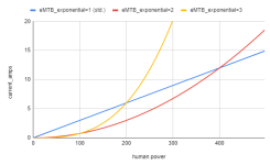
4. unlimited configurations are possible, for example:
this will be my motor output with an assistance level of 0.03 and eMTB_factor = 5:

Cattura.PNG

and this is in comparison the motor output at the same assistance level and eMTB_factor=10:

Cattura.PNG

In the afternoon I'll go for a ride testing the system and if the outcome willl be good I'll start working on the HMI part.
 
silvocross said:
2. eMTB mode is supposed to automatically increase the assist factor during uphill or high-load sections. This limits the need to play and constantly adapting the assist levels during offroad riding. It works very well and is used in all comemrcial systems, see as an example Bosch and Yamaha below:

csm_Bosch-eBike-eMTB-Mode-Chart_EN_3c9a2251d4.jpg
pw-x2_pict_002.png
Ok, I think I understand it and I agree - please move forward with the implementation.
I just saw your new message - great, we will need that examples and images to show on features and configurations page.

I think the result depends from user to user preferred ride mode. I like to do a constant human power and I shift gears to have the constant cadence I prefer, that means with that function the assist level will not change for me on uphills on offroad MTB.

What I though that commercial ebikes does is to have an IMU unit that could detect uphill and downhill and increase and decrease assist level on both cases.
 
Back
Top