Bafang M500/M600 thread

Not sure if there are any on here with spare motors, why not put a call out on

https://www.emtbforums.com/threads/bafang-m500-and-m600-motors.18717/

I know there are a few who have gone over to the M510 engine and have M500's as backups.

Good luck with the development, I suspect it maybe the only way we can update the M600.
 
Waynemarlow said:
Good luck with the development, I suspect it maybe the only way we can update the M600.
Thanks for the link.

I am thinking in using the VESC only for the motor control. Then, use a custom DIY board where every will be connected: brake sensors; throttle; torque sensor. This board will also connect to VESC using UART_0 and connect to the display using UART_1 (Easy DIY display).

This board will use the NRF52840 microcontroller (the same used on the Easy DIY display) and the firmware will be developed in Pyhton. This board will basically implement the EBike aplication: reading the various sensors and output commands to the motor controller, like setting the motor current and motor speed. It will also send data to the display and receive data for the user configurations done on the display.

This board with the EBike application, will be easy and fast to be reused on other devices like my TSDZ2 EBike motor controllers. I will also use it to my Xiaomi EScooter.

I already bought the Flipsky 75100 VESC motor controller to use on development and to install on the final, on my EBike with M500 and 52V battery. Currently, I have a Flipsky VESC 4.2 but it do not support voltages like 48 or 52V, only lower. I also have the NRF52840 board and I am starting the development of the EBike app in Pyhton.
 
I bought a used M500 for development, should arrive this week.

I did draw the schematic for the DIY version I plan to implement - all that was already tested on previous projects. The power to this board will be provided by the 5V output from VESC.

As can be seen, mostly is only wires. There are only 3 basic resistors + the CAN module (to communicate with the torque sensor) + the NRF52840 board. This board is connected by USB to PC, to be programmed with the (CircuitPython) Python application of EBike, yet to be developed. The debug of this python EBike application is done by serial port that is implemented on top of the USB connection.
The various sensors connections are really basic.

The communication for the display will also be UART and the power to the display will be the dame 5V from VESC.

ebike.png


And here is the schematic for the Easy DIY display - really basic:


For now, I have a very simple Python code that is sending data to UART1, to be connected to VESC. My plan for next days is to make a code that reads the throttle value and setup a motor speed and current based on the throttle values. It needs to read the throttle ADC as also to read and send by UART commands to the VESC -- here is the Github repository with current code and schematics:

https://github.com/OpenSourceEBike/EBike_EScooter_app_pyhton/blob/main/firmware/code.py
 
Sounds good Casainho, glad you were able to source a used M500.

Keep us updated please, most of us here can only admire your skills and speed at implementing this type of thing.
 
VESC is so popular..., there are many tools for it. I found a Python library to communicate with VESC, although this is more for a RaspberryPI or a PC, since that is a complex Pyhton that can not run on the limited CircuitPyhton of microcontrollers:


I will then implement just a basic communications with probably just 4 commands, like:
- motor get values (will get motor current, speed and battery voltage, etc)
- motor set current
- motor set speed
- send heartbeat (this needs to be sent regularly otherwise the VESC will stop the motor, which is a must for security as we can not put motor running and disconnect the EBike control board and the motor would continue running)

Also for reading the torque sensor on CAN, there is already a library the includes support for the CAN module to be used and also CAN communications, so, we will just need to to compared for the torque sensor command ID and extract the torque and cadence values. Here is an example:

 
I just got the M500 second hand motor, it was fast, thanks to Thomas H.

First thing I did were to remove the cover and original motor controller, and cut the motor wires on the original controller and solder to VESC. Took me only 1 minute to get the motor running -- note that when the motor do noise but shaft do not rotates, I was rotating the motor backwards and so it freewheels:

[youtube]iHcGs2x2Dq4[/youtube]

As you can see, I only needed to connect the 3 phase wires and it is running sensorless.

See also that there is a generous space where the original motor controller was, meaning the DIY EBike control board can probably be installed there and the only external board will be the VESC controller. The wires will need to be:
- 3 thick motor phase wires, as seen on the video
- 2 thin UART wires, for communication with VESC
- 2 thin wires, 5V and GND, from VESC to power the DIY EBike control board
 
Today I was able to send the VESC command COMM_GET_VALUES and receive the response. So I am now able to correctly communicate with VESC.

COMM_GET_VALUES get as answer a lot of different data, and that values, as seen in the middle of stream as 197, means battery voltage of 20V and also the 1 42 (1*255 + 42 = 297) means battery voltage of 30V -- I adjusted the voltage on my lab power supply and this way I did confirm I am getting the response correctly to the COMM_GET_VALUES command.

Next I need to implement the heartbeat / COMM_ALIVE, that EBike board must send at least every 990 milliseconds, otherwise VESC will keep the motors turn off. Only after this, I will be able to send the commands to set the motor current and motor speed, and then I will get the motor rotating as expected.

image.png
 
Currently the BESST software seems to upgrade itself and the loginbypass.py doesn't work anymore. At least for me. @CiDi or @bikelpl do you might have a look at it?

EDIT: Working now.. Copied the loginbypass.py from GitHub, but had to change api.besst.bafang-service.com to test.api.besst.bafang-service.com in run().

I also added the user-rfq tweak from @bikelpl:

bikelpl said:
Code:
userdata = json.dumps( {'code':0,'data':{'account_type':[1,2,3,6,7],'user':{'status':6,'org': {'id': 1340, 'type': 6}},'token':123}} )
 
I got the Bafang M500 motor running using a throttle. The code I did, reads the throttle value and maps that value to a motor current value, that I send to VESC using command COMM_SET_CURRENT.

[youtube]QEnLWcn1LbE[/youtube]

Here is the current EBike board. Black and red wires powers the EBike board from the VESC. Yellow and white wires are UART tx and rx, for communication with VESC.
The throttle has 3 wires. The blue is the throttle output analog signal and the others are GND and 3.3V that powers the throttle. There is one resistor of 100K, as seen on the following schematic:

image.png


And this is the current Python code of the EBike board:

 
fechter said:
Great work!
How’s the latency in throttle response?
The Bafang torque sensor outputs data every 10ms (100 times per second), so I would say at least 10ms is enough.

As seen on the code, the read_sensors_control_motor() reads the throttle and sets the motor current, every 2ms, so 5x faster than the torque sensor. My plan is to read all sensors there, at every 2ms, and then set the motor current - sure, there will be added latency, mainly due to the UART communications to VESC, still I think will it be negligible.

But the motor response should be configured on the VESC side (can be done wireless using the VESC mobile app), and I am not experienced on that but others probably are. But anyway, every parameter to be configured on VESC by his mobile app, can also be set by the EBike board (well, this EBike board uses the same NRF52840 that VESC uses to communicate with the mobile app, and the firmware for it is OpenSource and in C code, so there is potential to adapt that code on this EBike board with the Python code, so the EBike board would also work to configure the VESC and get real time data from the motor!):

 
Casainho, there are a number of VESC boards available ( I think the one you are using is for higher voltages and more current than needed ), are there any small VESC Boards of lower amp specs enough to shoe horn into the void left by taking out the Bafang controller ?

Edit: A quick look on the internet throws up this little beastie at 65mm x 18mm. It only has a burst amps of 40A and rated at 20A constant which is right in the ball park
https://www.sparkfun.com/products/18715
 
Waynemarlow said:
Casainho, there are a number of VESC boards available ( I think the one you are using is for higher voltages and more current than needed ), are there any small VESC Boards of lower amp specs enough to shoe horn into the void left by taking out the Bafang controller ?

Edit: A quick look on the internet throws up this little beastie at 65mm x 18mm. It only has a burst amps of 40A and rated at 20A constant which is right in the ball park
https://www.sparkfun.com/products/18715
If you go to the manufacturer page, that controller is rate up to only: Input Voltage: 3S-8S. I would say that controller is not for EBike application. But keep trying, maybe you will find something better.
 
Ah, sorry I only saw the 48V which normally means that you can go up a bit.

If you get a chance could you measure up what the size of the inner part of the motor where the old controller sits is. I think it maybe better to work backwards and find the max size and then look for components.

By any chance does anyone have the actual drawings of the motor as a dwg perhaps ?

Thanks.
 
Waynemarlow said:
If you get a chance could you measure up what the size of the inner part of the motor where the old controller sits is. I think it maybe better to work backwards and find the max size and then look for components.

By any chance does anyone have the actual drawings of the motor as a dwg perhaps ?
Around 55mm x 45mm. I simple do not expect to any VESC to get there. The original motor controller is optimized for that volume, I think is impossible to get something DIY there. But sure, a smaller board is always welcome.

Note that the Flipsky 75100 that I will use, is already small as possible and there are a lot of information about it, from other users, and that is important to decide to use it:


From the outside:


And here is my EBike frame, the motor controller cover, can be 3D printed to have a custom design for cables going through. As my frame is black, maybe I can 3D print with black plastic filament a box to hold the VESC motor controller and somehow be more or less integrated on the frame design:

 
OK last one before doing a proper research, note the size 35.5 x 21 x 13.8mm + connector lengths. Its 12 S but has 60V FETs and 15A constant but with the case 25A

https://teamtriforceuk.com/a50s-v2-2/
 
Waynemarlow said:
OK last one before doing a proper research, note the size 35.5 x 21 x 13.8mm + connector lengths. Its 12 S but has 60V FETs and 15A constant but with the case 25A

https://teamtriforceuk.com/a50s-v2-2/
Seems incredible small!! -- My batteries are all 58.8V when fully charged so that controller will not work for me. Who knows, maybe in future with a smaller motor like Bafang M820 if it works with a 36V battery / 10S. But this is the advantage of going modular and using VESC.

For now, I already bought 2 Flipsky 75100 that I will use on this project, one for my EBike and other for my EScooter. I will keep going with my current hardware. I have here 1 unit of the CANBUS MCP2515 module, that I will now connect to the torque sensor and I will try to read it.
 
I've already digitized the M600 board and put a .dxf file in this thread and captured a great deal of the VESC schematic. We've had some additional discussion of making a VESC style controller onto that board shape - so it would be a direct bolt in. With other boards, you could possibly 3D print a cover, though on the OEM board, the cover is the heat sink for the mosfets. They don't need a lot of cooling, but will need some - and of course would need more cooling for even higher power use. So some additional considerations if a plastic cover is used.

[Edit - catching up on some reading here, I see this is already mentioned several posts back, so will leave here for reference only!]
I am curious, it seems some months ago, Vedder demonstrated sensorless operation via HFI. Seems this would be useful for us and would get rid of the magnet sensor requirement which would free up board space, reduce cost and simplify other things. Though I think this means we need a VESC 6 or better board.

https://www.youtube.com/watch?v=H-6qzmeCNtw
 
4πr^2 said:
[Edit - catching up on some reading here, I see this is already mentioned several posts back, so will leave here for reference only!]
I am curious, it seems some months ago, Vedder demonstrated sensorless operation via HFI. Seems this would be useful for us and would get rid of the magnet sensor requirement which would free up board space, reduce cost and simplify other things. Though I think this means we need a VESC 6 or better board.

https://www.youtube.com/watch?v=H-6qzmeCNtw
I recorded this my last video using the HFI silent version. If I use the stable VESC tool software, I can not access to that option. If I use the beta version, I can update my controller firmware to version 6 and then this beta VESC tool will let me choose the HFI silent version.
I do not know how to compare with other boards, but you can see the one I use is the previous "old" version and for me it seems to work very well:

[youtube]QEnLWcn1LbE[/youtube]

And about the Bluetooth board for VESC, I just found that the one used by VESC is the same NRF52840 and so the EBike board should probably replace that board, having simultaneously both functions: EBike application + Bluetooth for connection to VESC tool and mobile app: https://github.com/vedderb/nrf52_vesc
 
Hello everyone :) :bolt:
I think this board will be perfect.
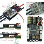
Flipsky Mini FSESC 4.20
Amps: 50A continuous, instantaneous current 150A
Voltage: 8V-60V

https://flipsky.net/products/mini-fsesc4-20-50a-base-on-vesc-widely-used-in-eskateboard-escooter-ebike?gclid=Cj0KCQiA99ybBhD9ARIsALvZavVaAnDU-MhcMW0kEpoKesJQmxasgB5SMJfCVhERH4lAPhwHFGmgxrQaAk3IEALw_wcB

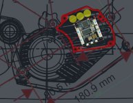
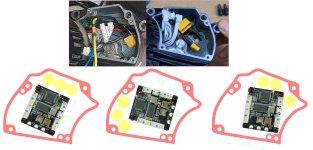
I made simulations based on the data I was able to get and it should fit. There will still be space for EBike boards.
I think that the use of the board inside will have a positive effect on the inductance reading because the phase conductors will be short. Accurate Inductance Reading = Better Sensorless Control.
 

Attachments

  • 1.jpg
    1.jpg
    353 KB · Views: 287
  • 2.jpg
    2.jpg
    182.4 KB · Views: 286
  • 3.jpg
    3.jpg
    453.7 KB · Views: 287
rezystor1990 said:
Hello everyone :) :bolt:
I think this board will be perfect.
Flipsky Mini FSESC 4.20
Amps: 50A continuous, instantaneous current 150A
Voltage: 8V-60V
I guess you are right!! I just measured and I see the same you put in your pictures. If I am looking for a small battery, small motor, maybe would be better to use a 36V motor and 36V battery. And then that smaller motor controllers will work well.

Does anyone knows if Bafang has different motor versions for 36V and 48V? just like on TSDZ2, where the motor coils are really different on 36V and 48V versions?

For the EBike board, we can also go smaller if using this NRF52840 board:
 
The outer cover to the motor, could we not get a CNC'd aluminium cover made.

Casianho if you ever need the likes of the smaller Flipsky module to proceed do ask, I'm sure a few of us would contribute to the development cost.
 
Waynemarlow said:
The outer cover to the motor, could we not get a CNC'd aluminium cover made.

Casianho if you ever need the likes of the smaller Flipsky module to proceed do ask, I'm sure a few of us would contribute to the development cost.
I am looking for 15 amps only, so 560W on 36V motor / battery. I hope I can get that 15 amps without without any special cooling, so I would go with with plastic 3D printed cover.

Yes, If there is a controller small like that one, I would prefer to go with it and probably the 48V battery 13S, that seems the limit to that controllers??

A developer told me the controller I am using do not support HFI silent and even I selected it, it will default to the no silent version. So I think is important to choose very well the controller...
 
Does the Filpsky mini in the link above not fulfil our requirements ? 60V with 100V caps, more than enough amps and it will fit into the engine bay. The only downside I think is it’s not the latest VESC but that is something above my knowledge and can it be upgraded to the latest firmware ?

Whatever you do it would be appreciative by many of us to consider the M600 units, where probably 1000W’s should be enough, anymore and the M620 motor should be the consideration, but that engine already seems to have been catered for.
 
The only downside I think is it’s not the latest VESC

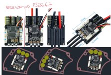
Will FSESC6.7 be enough? Phase currents must be measured for silent control HFI. I think the new version has it? You can always implement an encoder if there is a problem with the sensorless control.

https://flipsky.net/products/flipsky-mini-fsesc6-7-pro-70a-base-on-vesc6-6-with-aluminum-anodized-heat-sink

Continuous current: 70A; instantaneous current:200A
Voltage: 14V-60V


I am looking for 15 amps only, so 560W on 36V motor / battery. I hope I can get that 15 amps without without any special cooling, so I would go with with plastic 3D printed cover.

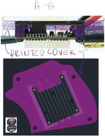
Why only 36V? The board will work without any problems on 13s 48V (54.6V), even from 14s (58.8V). BMS protects us from overvoltage, so it is neither voltage nor current for us. You can prepare a printed cover while keeping the heat sink (sketch below).

Casianho if you ever need the likes of the smaller Flipsky module to proceed do ask, I'm sure a few of us would contribute to the development cost.

I am happy to support the project, for me it is interesting for use in G510 / M620.
 

Attachments

  • 7.jpg
    7.jpg
    545.9 KB · Views: 214
  • 8.jpg
    8.jpg
    227.1 KB · Views: 215
Back
Top