Bafang M500/M600 thread

Finally I got the torque sensor readings working. Turns out the issue was because I forgot to put the 75 ohms resistor on the CANBUS. But also it was needed a change to the Adafruit library, because this board uses a 8MHz crystal and Adafruit boards uses 16MHz.

Here is the torque sensor data:


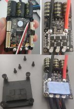
And here is the current state of the board. Yes, the CAN board is big:


Before start doing the EBike application, here is what is working and what is missing:
- [x] Throotle read
- [x] Torque sensor read
- [x] Brake sensor read
- [x] Wheel speed sensor read
- [x] VESC motor control
- [ ] Display

So the display communication will be my next step. The display I will be using is the Easy DIY display.

If anyone prefers a bigger and color display, even easier to build, this boards with ESP32 + display, seems perfect. It only needs 4 wires to be soldered, from the EBike board: 5V, GND, UART TX and RT. It also needs a 3D printed shell.

There is no EBike display application for that board, but I assume it can run Python and then an application can quickly be developed. Being Python, that means the same application will work on other similar boards - with bigger or smaller displays.

 
Excellent information and instructions.

I know this is an old thread, but does anyone know if this process would work with the Bafang M410 ?
(Controller/display is the DP C07.C CAN type)

(Came with an Eskute Netuno Pro)

Thanks!


CiDi said:
To configure the Bafang M500 / M600 motor without using the BESST programmer, you can use this interface.

Link interface USB to CAN on Amazon:
https://www.amazon.co.uk/USB-Converter-Module-Raspberry-Zero/dp/B07Q812QK8/ref=sr_1_2?dchild=1&keywords=usb+to+can+innomaker&qid=1604409709&sr=8-2

Link cables Bafang HMI M500/M600 on e-bike-technologies:
https://www.e-bike-technologies.de/index.php/en/connectors/connectors-signal/connectors-higo-mini-f-series/higo-b5-f-detail
https://www.e-bike-technologies.de/index.php/en/connectors/connectors-signal/connectors-higo-mini-f-series/higo-s5-f-detail

Below are the software and the instructions for configuration and use.
 
I just found I can connect using Bluetooth to the EBike board, for development, program and debug the code, wirelessly!! I can do it using a PC or a mobile phone, meaning I will be able to be outside riding and developing or tweaking the EBike software or the VESC motor controller parameters - how cool is that?

Comparing to develop firmware for the original motor controller... with very specific and hard development tools, with limited knowledge about the circuit and expensive parts...

After connecting by Bluetooth, I go to https://code.circuitpython.org and I am able to open the code Python files, edit, save and run the code, as also use the serial port for debug:


And here is the code to read the torque sensor data by CANBUS:


And yesterday I received the Flipsky 75100 VESC, it is really small but as expected, not enough to be placed inside the motor:
 
casainho

Just wanted to say thanks for your awesome work on this. I wouldn't have the skills to do any of the stages you have already done and are yet to do, let alone implement what you finally produce, but I'm really enjoying watching the journey.
 
Finally I have the display working, here is the current status:

Before start doing the EBike application, here is what is working and what is missing:

- [x] Throotle read
- [x] Torque sensor read
- [x] Brake sensor read
- [x] Wheel speed sensor read
- [x] VESC motor control
- [x] Display
- [ ] EBike application
- [ ] Install this system and this Bafang M500 on my EBike, test and make the final developments

Current Pyhton code: https://github.com/OpenSourceEBike/EBike_EScooter_app_pyhton/blob/main/firmware/main.py

My next step is start thinking on the EBike application. I will use my EBike on an event this weekend so I will keep the original motor up to next Monday, after that and up to January 2023, I should finalize this project in a way I can ride my EBike on next events. As I can develop and program by Bluetooth, with a PC or my phone, the EBike application software, I will always be able to fine tune anything at last minute before any riding or even during a ride -- because I am pretty sure it will take time to fine tune the motor torque curve response, throttle curve, etc.

As you can see on the video, the battery voltage, battery current and motor power, can be seen on the display. Note that this values are read from the VESC and so they are slightly different from the ones seen on the lab power supply.

Video: https://www.youtube.com/shorts/X1hcIg9wIr4

[youtube]X1hcIg9wIr4[/youtube]

I also received the PHB 2.0mm 2x3P connector, so this way I can connect my wires to the torque sensor using this connector. I also bought the PHB 2.0mm 2x11P so I will be able to use the original cables for the display, brake sensors, throttle and wheel speed sensor. The plan is that I keep the original cables and I can go back easily to the original motor, just by installing in the place on the frame and quickly change to the original display, this, in the eventual case that I will need the EBike ready for an event and this OpenSource EBike system is not ready yet.

 
Casainho, I was a bit doubtful about having an external VESC controller and interface electronics outside of the motor casing, but I'm starting to wonder whether its the simplest solution. After all its just wires and another enclosure and in most EBikes up near the head stock there is some space.

A question, the length of wires required to go from the motor up the length of the frame to the headstock area, how much lag do you think this would create ?
 
Waynemarlow said:
Casainho, I was a bit doubtful about having an external VESC controller and interface electronics outside of the motor casing, but I'm starting to wonder whether its the simplest solution. After all its just wires and another enclosure and in most EBikes up near the head stock there is some space.

A question, the length of wires required to go from the motor up the length of the frame to the headstock area, how much lag do you think this would create ?
Anyway, for now I will go with the outside electronics. If I wanted to do the same on my TSDZ2 EBikes, that would be the same way anyway. Only after I have everything working, after solving any eventual issues that will happen, we can think in improving but putting everything inside the motor.

I do not know yet length of the wires. Look at the picture of my frame and the motor controller cover. I will want to put the VESC + EBike controller board, really near the cover. I hope I can get a creative way with 3D printed parts, to fix all this to that carbon frame:


On my Xiaomi EScooter, there is enough room (even for 2 VESCs):

Xiaomi-Mpower-365-Motor-Vesc-no39.jpg
 
Hi, congratulation for this great project
Do you think that your TSDZ2 EBikes card could work on with M420 canbus motor ?
 
mroupi said:
Hi, congratulation for this great project
Do you think that your TSDZ2 EBikes card could work on with M420 canbus motor ?
It will always needs some knowledge and development for the specifics of each motor. Like, how is the torque sensor? How to read the torque sensor?

For a developer like me, it would be possible to do it relatively fast, specially if it uses the same torque sensor of M500 M600. I am sharing all the knowledge, not hiding anything, so I hope other developers can join and adapt for their EBikes and also share the results to help even more users.
 
Yes , I hope
I'm not a great developper as you
but the toque sensor seems to be the same for M500/M600/M420
 

Attachments

  • Capture.JPG
    Capture.JPG
    20.6 KB · Views: 1,106
mroupi said:
Yes , I hope
I'm not a great developper as you
but the toque sensor seems to be the same for M500/M600/M420
Yes, so the solution to M500/M600 should be similar to M420. I also hope the same for M820, that I wish to have in future in a gravel EBike.
 
casainho said:
...

2. Back emf / regen voltage spike: as I already explained, since this motor freewheels, I think we take the risk although explaining to users to avoid rotating the motor with the battery power unconnected.

Good question about the motor phase. I think no one knows what is that value on the original firmware. My guess is that motor will handle at least twice of the battery current, so for my M500 (36V motor) of 500W, 24A battery current and 48A motor phase current.

...

How about the situation when we backup the bike on reverse? The motor clutch will engage and motor will rotate backwards as well. Does it creates spikes as well?
 
szkuba said:
casainho said:
...

2. Back emf / regen voltage spike: as I already explained, since this motor freewheels, I think we take the risk although explaining to users to avoid rotating the motor with the battery power unconnected.

Good question about the motor phase. I think no one knows what is that value on the original firmware. My guess is that motor will handle at least twice of the battery current, so for my M500 (36V motor) of 500W, 24A battery current and 48A motor phase current.

...

How about the situation when we backup the bike on reverse? The motor clutch will engage and motor will rotate backwards as well. Does it creates spikes as well?
I do not know. I guess we will need to figure this out.
 
I would like to share the information about how I plan to implement the EBike application. As you may know, there is a M600 controller developed by Luna based on VESC. The source code is on VESC Github repository, and based on it as also on more EBike examples on VESC source code, I got this information:

1. Torque sensor

After reading the torque sensor value, it is scaled based on the assist level factor as also is now relative to desired motor current:


After, a ramp curve is applied, so the increase rate of motor current value is controlled. This way is guaranteed to not be to much strong to avoid damage of the plastic gears, etc. The final output value will later be set as the motor current:


About the torque sensor reading, as Luna did only the motor controller based on VESC, the M600 torque sensor should be the original. The code they use is equal to the one I use to read it (they call it LUNA_TORQUE_SENSOR_ID but is as just the same CAN ID: 0x01F83100 as our motors.
BUT, they only read the torque value, they ignore the cadence value, so they do not use the pedal power:


And here is the code that calculates the assist level scaling (9 assist levels), that is applied to the torque sensor value:


2. Torque sensor

After reading the throttle, an exponential curve is applied, so a change of throttle at begin gives a low motor current change but the same change at the end of throttle range, will give a high motor current change.
As seen on the code, after the exponential curve is applied, the same ramp curve as for the torque sensor, is applied:


And here is the code of the exponential curve:


So I have a pretty good understand how the EBike application should be done, even because I did it from scratch on the KT and TSDZ2 motor controllers.

A big advantage this time, is that I will be using Pyhton and direct wireless programing, that means in my phone I will be able to open the Python text files, change any line of code, save and it will immediately run that new code. And there will be almost no risk to damage the motor, battery or the VESC, because I will be changing only the EBike application, and not the VESC motor controller code because it is inside the VESC and can not be changed.
 
@rezystor1990, you did a great work showing that is possible to put this small VESC controller inside the original motor. Can you help further in like design and 3D print the part to hold the encoder board + the VESC?

I can help but I don't have an M600/500 engine. I would need information, measurements to make such a model:
- scan of the plate gasket
- scan encoder board
- scan of the original driver plate
- dwg/dxf of the engine if anyone has it
- photo of the engine taken with a large focal length perpendicular to the engine

I already have FSESC mini.

Yes, the CAN board is big:

Maybe another SoC with CAN support? Minimizes to the number of elements.
 

Attachments

  • 12.jpg
    12.jpg
    327.4 KB · Views: 1,029
rezystor1990 said:
@rezystor1990, you did a great work showing that is possible to put this small VESC controller inside the original motor. Can you help further in like design and 3D print the part to hold the encoder board + the VESC?

I can help but I don't have an M600/500 engine. I would need information, measurements to make such a model:
- scan of the plate gasket
- scan encoder board
- scan of the original driver plate
- dwg/dxf of the engine if anyone has it
- photo of the engine taken with a large focal length perpendicular to the engine

I already have FSESC mini.

Yes, the CAN board is big:

Maybe another SoC with CAN support? Minimizes to the number of elements.
Well, I am now in a phase that I need to test the magnet encoder on the VESC so I will design and 3D print, as I have all the parts and tools needed. Only when I have decided to use or not the magnet encoder, I will start developing the EBike application.

I will also start miniaturizing the EBike board, by cutting the extra not needee board as also the USB part of the NRF52840 board, as I will program it only by Bluetooth. I want to start prepare the final hardware that will be installed on my EBike, starting on next Monday.

Maybe I will keep my current EBike board for development at my bench.

For CAN, there is no SOC with full CAN support, at least an IC must be added externally.

Thanks for the pictures of the Mini FESC. We will need to buy new capacitors when removing that ones... So maybe we can go with a bit smaller ones if possible??
 
Got the very first design of the motor controller cover. It is almost perfect, just an hole that is slightly of the place.

Next step is to add the exact place for the magnetic encoder board. As I have here the original M500 and motor controller, should be easy to do that. Images of current state:


Casainho, you certainly get your teeth into these projects and it always staggers me just how much progress you make in such a short time.

Looking good.
 
I have some unexpected delays:
1. My oscilloscope stopped to work and I had to buy a new one that will take 2 weeks to arrive.
2. I could not make working the magnetic sensor board. It is very hard to solder the wires due to the thin pads. I could check that the sensor was changing the PWM value output based on the magnet position, but o VESC I always got 0 degrees and I could not check the SPI communication because I have no oscilloscope.

I decided to buy this magnetic sensor boards because the pads to solder the wires are much better:


Since I can not have the magnetic sensor, I decided to move forward using the HFI sensorless mode. For now, I only connected the Flipsky 75 100 to Bafang M500 and it works well as expected. I will take next days to install all the system on my EBike:

[youtube]AXrD0Hyv8fg[/youtube]
 
I used silicone to insulate from water ingress on my Flipsky 75100 VESC motor controller, but I only had white silicone, I wish I had black. Anyway, may plan is to 3D print a black enclosure later:


And here is it on the place I will install it, on my EBike frame. As you can see, the cables will be like that to go inside the motor, I just need to remove the metal cover with the original Bafang motor controller:


As I was trying to install the EBike board inside my EBike motor, I decided to better testing the wireless programming and turns out that over Bluetooth, the technology developed by the CircuitPyhton guys is not mature and has a lot of issues, it simple do not work enough yet.

Then I tried the ESP32 boards I have with me (I never used ESP32 before) and the wireless programming works very well, in fact, it is perfect! So my plan now is to move to a ESP32-S3 because it is the one I have here with me (this should be very fast, thanks to Python, as the firmware is not specific for any board!). I also have a small board with ESP32-C3 but it has not enough free pins, but it still works perfect for wireless programming.

This is the first page I see when I connect with the internet browser to http://circuitpython.local:


The next page is this one. Yes, we can setup a password, means it should be hard for anyone trying to erase or access our own devices. This password as also the wifi network configurations, are setup on a TXT file, when we connect the board by USB to a PC, so it is straightforward:


Here when I click on the previous page, on the Full Code Editor, then I can open any file, created or delete. This is where we can edit and run the code wireless in real time:


And then we can see the Serial Terminal where we will see the debug information, this is great to debug the firmware as also see sensors data in real time, like if we want to check the torque sensor values, etc:
 
Wasn’t there quite a bit of development on the TSDZ2 done by one guy using the ESP32 board, he has all the mobile phone Apps and such like already set up, maybe worth conversing ?

https://endless-sphere.com/forums/viewtopic.php?f=30&t=103318
 
Waynemarlow said:
Wasn’t there quite a bit of development on the TSDZ2 done by one guy using the ESP32 board, he has all the mobile phone Apps and such like already set up, maybe worth conversing ?

https://endless-sphere.com/forums/viewtopic.php?f=30&t=103318
Very different. Since I remember, the EBike application were implemented on TSDDZ2 motor controller and ESP32 were more to add Bluetooth for the mobile app comunication. Nothing can be reused to make Bafang motor running or the EBike application. And on that time, I think Python were not available for this microcontrolers.

Here the focus is to implement the EBike aplication on Python, on this external board and not on the motor controller, and program wireless, in real time using a mobile phone while we are outside riding.
 
So I finalize the move from the NRF52840 to the ESP32-S3 board (purple board). Everything is working as before.

Advantages of going with ESP32-S3:
- Wireless real time programming and debugging (using prints) with a smartphone or PC
- 64MHz cpu clock VS 240MHz cpu clock. ESP32-S3 is 3.75 times faster! this is important because Python is slow, so this should give a better safe margin for this project.

Disadvantages of going with ESP32-S3:
- around 230mA of current!! while NRF52840 would take only about 1/4 of that, like 60mA. This issue is that this current flows from the VESC on a 5V wire and it is a lot and may be near the limit that VESC can provide, so we never know if there will be a problem because of this. Also, the higher the current as it is, the higher the interference on the surrounding cables like the UART for communications with VESC, so having the potential to more problems on the communications.

Picture of the working prototype on my bench:


I am also documenting so later I can write the How To Build page, like here are the connections and notes to the torque sensor connector:


How to identify/check the torque sensor pins
Power pins:
- measured resistance between 5V and GND pins: 33.3 Kohms.
- measured in continuity / diode mode: 0.98 volts between GND and 5V and 0.44 volts with inverted polarization of multi-meter leads.
- with this information you can easily distinguish each pin. You should be very careful to not exchange them otherwise you may burn your torque sensor and/or board EBike application board.

CAN_H and CAN_L pins:
- measured resistance between CAN_H and CAN_L pins: 47.7 kohm
- measured in continuity / diode mode: OL / open / no voltage which ever is polarization of multi-meter leads.
- it is not possible to identify which is the CAN_H and CAN_L, however, if you exchange them, nothing will be damaged but reading the torque sensor will not work.


My next step is to miniaturize this EBike board (purple and blue boards) and install it inside the Bafang M500 - I checked already that wireless programming still works like that if I keep the cover as a 3D printed plastic part.
 
I just installed the EBike board on the Bafang M500 motor, but for now, only on the desk and not yet on my EBike -- soon I will :D

Here is a picture, note the EBike board powered on with his LEDs. All that wires/cables are final, and I put a 4 wires connector to the VESC UART and 5V and GND wires, this way I can quickly disconnect the VESC from the EBike board, to make easy for final installation:


Here is a video:

[youtube]yVl1XtECqY4[/youtube]

And here are screenshots from my phone, accessing wireless to the EBike board, I can edit here the firmware, save it and it will run:


And here the firmware outputting the torque sensor torque raw value, the calculated weight kgs and the cadence. Interestingly, when the motor runs as seen on the video, there is cadence value:


And here is the EBike board, with short wires and carefully soldered. On this side, we see the ESP32-S3 board:


On this side, we see the MCP2515 CAN module board that let us read the torque sensor values:


So, for now, the EBike board reads the torque sensor and control the motor by sending commands to VESC. What is missing? is missing the brake sensors connection; wheel speed sensor connection and display connection.

Wheel speed is not a priority, I will leave for the end of the project. Display, it is not a priority for now as I can see the EBike data sent wireless to my phone, that is enough for now. To have my EBike working, I just need to "plug" to torque sensor value to the VESC motor current - and I also need the brake sensor working, this is a must!!
 
Went for a quick installation of the EBike board on my EBike. As you can see, I were able to remove the original motor controller directly, so it was very fast. It is fast and easy to access to all the connectors: battery; 3 motor phases; torque sensor; motor temperature sensor and the big connector that has the connections for the outside like display and brake sensor:


EBike board installed and powered on. See where I placed the VESC Flipsky 75100. For this test I left the motor 3 phase wires disconnected, as I did not want to risk to motor rotate - next time I need to find a way to keep the wheel on the air:


Now I was able to apply my weight on the pedals and see the measured torque value on my phone - as we already know, this torque sensor can only measure up to 40kgs:


I just in time, I received today the 2X11P 2.0mm PHB connector, that will let me wire the brake sensor, display and wheel speed sensor!! I already had with me the 2X3P 2.0mm PHB connector for the torque sensor:

 
Back
Top