Bafang M500/M600 thread

casainho said:
So I finalize the move from the NRF52840 to the ESP32-S3 board (purple board). Everything is working as before.

Advantages of going with ESP32-S3:
- Wireless real time programming and debugging (using prints) with a smartphone or PC
- 64MHz cpu clock VS 240MHz cpu clock. ESP32-S3 is 3.75 times faster! this is important because Python is slow, so this should give a better safe margin for this project.

Disadvantages of going with ESP32-S3:
- around 230mA of current!! while NRF52840 would take only about 1/4 of that, like 60mA. This issue is that this current flows from the VESC on a 5V wire and it is a lot and may be near the limit that VESC can provide, so we never know if there will be a problem because of this. Also, the higher the current as it is, the higher the interference on the surrounding cables like the UART for communications with VESC, so having the potential to more problems on the communications.
there is something wrong…
For me 87mA with screen and BLE com. !!!
microcontrôleur ESP32-S 240 MHz Tensilica LX6

2mjj.jpg
 
SUPERJC said:
casainho said:
So I finalize the move from the NRF52840 to the ESP32-S3 board (purple board). Everything is working as before.

Advantages of going with ESP32-S3:
- Wireless real time programming and debugging (using prints) with a smartphone or PC
- 64MHz cpu clock VS 240MHz cpu clock. ESP32-S3 is 3.75 times faster! this is important because Python is slow, so this should give a better safe margin for this project.

Disadvantages of going with ESP32-S3:
- around 230mA of current!! while NRF52840 would take only about 1/4 of that, like 60mA. This issue is that this current flows from the VESC on a 5V wire and it is a lot and may be near the limit that VESC can provide, so we never know if there will be a problem because of this. Also, the higher the current as it is, the higher the interference on the surrounding cables like the UART for communications with VESC, so having the potential to more problems on the communications.
there is something wrong…
For me 87mA with screen and BLE com. !!!
microcontrôleur ESP32-S 240 MHz Tensilica LX6

2mjj.jpg
That is good to know.

Here are the values of max current taken from the datasheets:
- NRF52840 max current: 40mA (with Bluetooth)
- ESP32-S2 max current: 310mA (with Wifi + Bluetooth)
- ESP32-S3 max current: 260mA (with Wifi + Bluetooth)

I may also be measuring not so well the value due to my cheap lab power supply. Also, the CircuitPython, I think it enables wifi and I would say the code is not optimized for low power - I guess you are using C++ and only enabling the peripherals you need.

For now it seems I have no issues, maybe because the wires have a nice thickness and are not that far from VESC. But for display, with the big thin long wires of Bafang M500, I would say it can be a problem.
 
Yes Wifi need more mA
Use only for SetupRtcTime, OTA, ….
..and I turn off the wifi when I no longer need it
After I use BLE only

//========[C++ wifi stop]=======
WiFi.disconnect();
WiFi.mode(WIFI_OFF);
 
I wired the brakes signal to the EBike board. Unfortunately, ESP32 has weak internal pull-ups and so I had to add and resistor on EBike board from the 3.3V to the brake signal ESP32 input pin.

This were quick early tests, but here a video of me pushing the pedals with my hand, and the motor reaction to it: https://www.youtube.com/watch?v=Xki6n73GpXk

[youtube]Xki6n73GpXk[/youtube]

The piece of code that reads the torque sensor weight value in kgs and maps to the motor current:


I found that the cadence read value from torque sensor is not stable, sometimes spikes and other times is just zero while the pedals are rotating at a medium value like 60 rpm. So on that piece of code, I just used the torque value.

NOTE: the code is missing the current ramp, to keep the current increase in control and slow, to avoid damage of the gears, etc. Still, I did some very short rides and it seems to work very well, It made me happy!! and as you can see, both motor start and stop, is not noisy, it is similar to original motor firmware, which is good!!

The firmware as also a task code to output some useful data, I get this in real time in my phone:
1. torque weight value in kgs
2. cadence
3. brake state
4. motor current (read from VESC)


My next step is to implement the motor current ramp. Then probably I will connect the display and start riding my EBike while I will be tweaking the firmware to have the motor response I am looking for. In begin of February I will have some MTB events, so by then I hope to have all the system ready, this means also everything water resistant!

And here is the brake sensor connection on the big connector inside the motor:


Code and other information are on Github: https://github.com/OpenSourceEBike/EBike_EScooter_app_pyhton
 
I updated the schematic to remove the NRF52840 board and replace with the ESP32-S3 board and reflect my latest working version. I also added the motor temperature sensor reading, that should be a 10Kohms NTC. I think this is mostly the final schematic!!

 
For debug, I can print the values and see in real time on the PC or on the mobile phone. But also, today I added code for that same data to be recorded on the memory of the board, as a CSV text file that I can later see on PC as graphs.
On the graphs bellow, this is the data by ascending order:
1. torque sensor weight in kgs (seems to measure very well. That moments that value go to zero is because the motor was rotating fast and is then hard to apply torque on the pedals - hence the very high value of cadence!)
2. torque sensor cadence value (even if I am pedaling, the values are sometimes zero)
3. brake sensor state (never did pressed the brakes)
4. battery current
5. motor current

It is raining and so I can not test and improve the EBike algorithm. I had to change the VESC sensorless HFI configuration, to improve it. It seems to work ok for now but I wish I could improve it but I lack experience doing it.

When the rain stops, I will be able to continue with the tests...

 
Bafang M500 max motor current

VESC motor auto-detection algorithm, suggest that M500 max motor current to be around 51 amps, so, I would say we should be able to configure it to be max of 50 amps - and for sure, use the motor temperature sensor and reduce this current as soon the motor hits the 80 degrees Celsius.

I was expecting to use only 20 amps as max motor current, because since it is a 500W motor on a 36V battery, it means max battery voltage will be around 14A, so I would use for motor current twice that value: 28A. But using 50A is about 1.8x more :D

Any suggestions? Anyone have a guess how much M500 can handle? and how much should we use to be on the safe side (I mean, also to not damage the gears, etc).
 
szkuba said:
When you say "motor current" is this equivalent to phase current?
This are the values I read from VESC, for battery and motor current:
- mc_interface_read_reset_avg_input_current()
- mc_interface_read_reset_avg_motor_current()

You can see them on the VESC source code: comm/commands.c
 
1. Then i would say "traditional" approach with phase current @ 2,5 x of battery current should be ok for a start. Then watching temperature increase at low cadence/ high load you can decide to add more.
2. So to your impression is cadence reading useful or not at all? can we use it for power calculation/low cadence current adjustments?
3. In regards to torque saturating at some point
2022-12-28 18_19_31-Moment i Moc - V5 na stronę_ENG.ods - LibreOffice Calc.png
i have generated the graph based on this scientific paper: https://www.researchgate.net/figure...ity-ie-cadence-and-power-output_fig1_49284193
so with torque sensor saturating at some point (50% of rider max pressure) it should look like that (yellow line):
Then applying this to cadence graph will look like that:
2022-12-28 18_19_43-Moment i Moc - V5 na stronę_ENG.ods - LibreOffice Calc.png

when we apply this to typical torque graph (proportional to phase current i think ) it look the yellow line shall be more or less ok. Can be simulated @ ebikes.ca https://ebikes.ca/tools/simulator.html?autothrot=false&motor=MBBS02&mid=true&gear=1&throt=100 So you can modulate the motor with adjusting the phase current in amps proportional to torque read.
2022-12-28 18_42_25-Motor Simulator - Tools — Mozilla Firefox.png
 
szkuba said:
2. So to your impression is cadence reading useful or not at all? can we use it for power calculation/low cadence current adjustments?
Nice all this graphs and information.

About the cadence, I don't know yet. For now I only know I see that zeros and that also the VESC code for the Luna controller do not use the cadence, only the torque value. See the code bellow. Also, the way my M500 respond to the pedal, I am pretty sure original firmware do not use the cadence, only the torque to then define the motor current.


The CAN messages have error CRC protection, so I do not think it is an error on transmission. Here is the data package from the torque sensor:


I never looked at the last byte, maybe it can give a clue for when the cadence value is not valid??
 
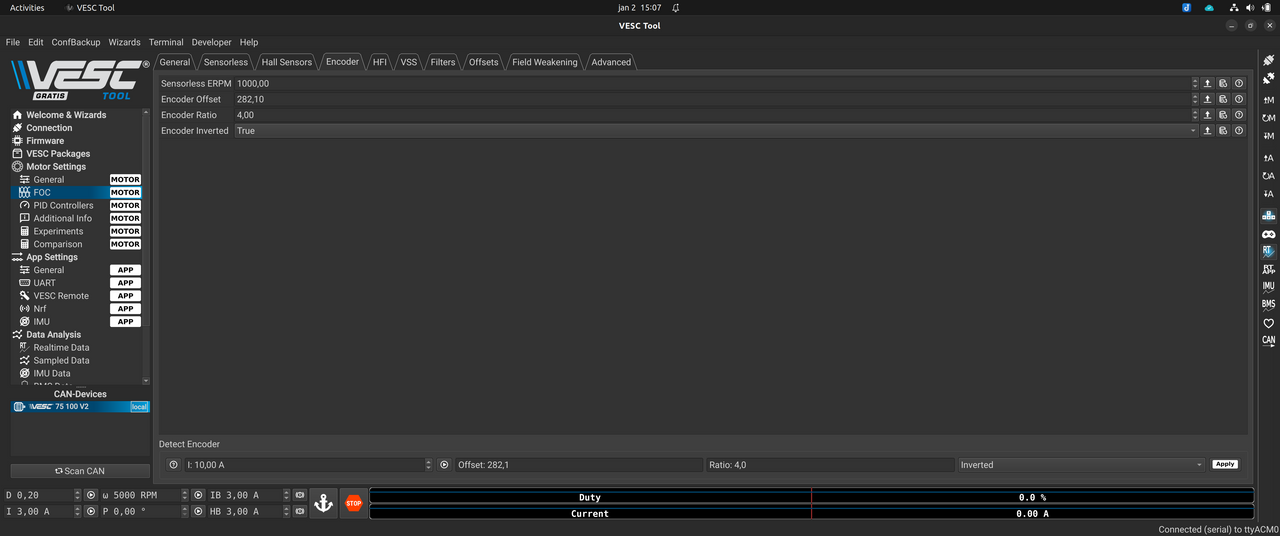
I got the VESC working with the magnetic encoder sensor, just like the original motor controller and firmware does.

Previously, after I tried the motor current ramp up, I could understand the HFI sensorless do not provide a soft motor startup. Even later I tried to follow the VESC tutorials for setup the HFI values and for some reason it does not work on this motor (motor specifics?? Flipsky 75100 issues ??).

So I received yesterday the AS5047D magnetic encoder board, did some tests to learn how to use it and finally I were able to make it working with VESC. I found that this board can be far away from the magnet and it will still work well, even with some misalignment related to the magnet.

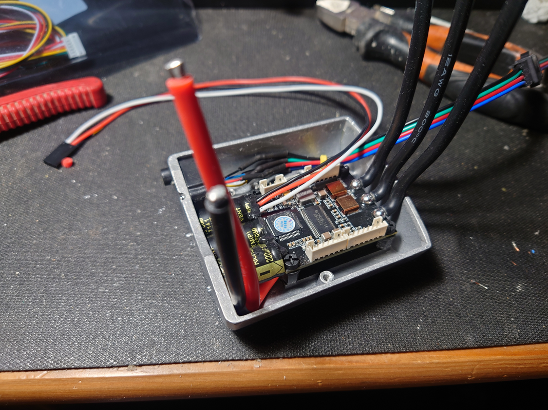
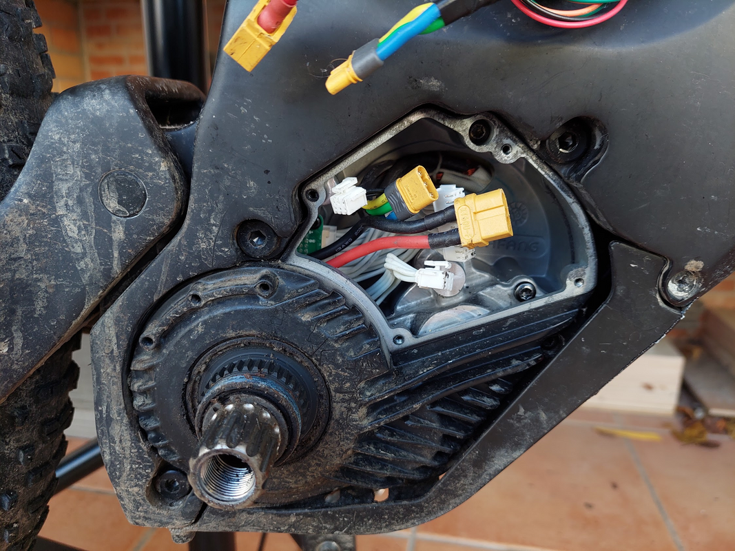
To get the AS5047 magnetic encoder working with Flipsky 75100, I had 2 issues:
1. The SPI wires to read the AS5047 are the same for the hall sensors and so the low pass filters (capacitors and resistors) on the hall sensors circuit (inside the Flipsky 75100), had to be removed. After this, the hall sensor / SPI wires can only read 3.3V signals, so I had to configure the AS5047 board to work with 3.3V (I took the 3.3V to power the AS5047 board, from the EBike board).
2. Two hall sensor wires are incorrect labeled on Flipsky 75100 documentation - HALL 3 should be swapped with HALL 1 (what would be SPI SCK and SPI CS wires, need to be swapped).

So, here are the low pass filters on hall sensors circuit -- original Flipsky 75100:


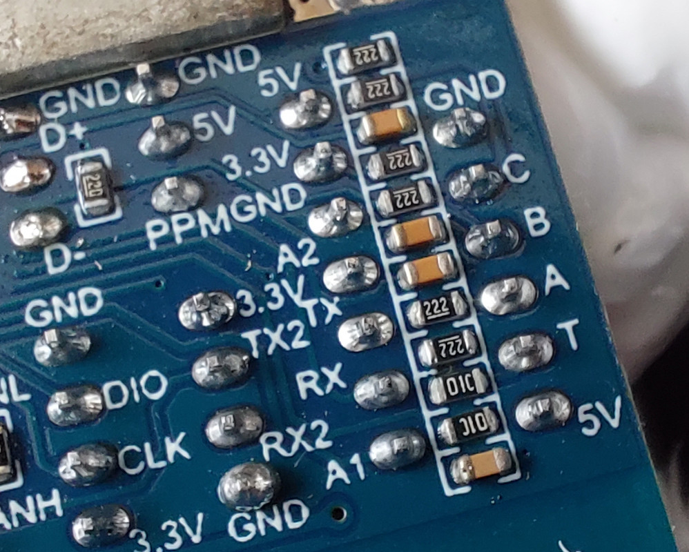
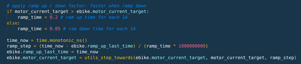
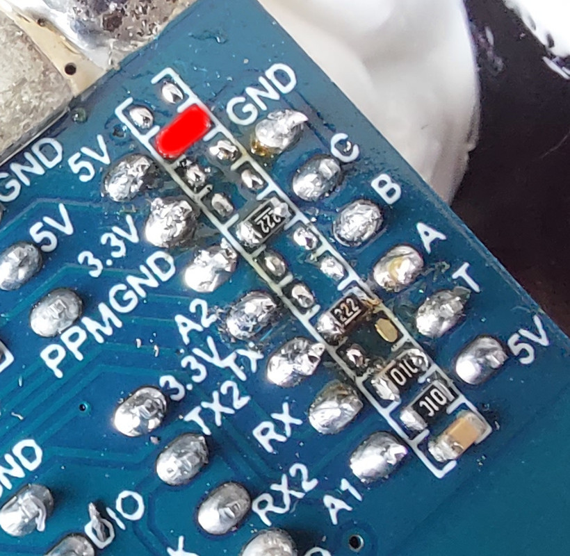
I had to remove the capacitors and resistors as seen on the image. Plus, at red, I had to remove that resistor and solder a small wire / shunt. That is the path of SPI CLK and I saw the signal a bit deformed with the original resistor, but without it, after soldering that wire / shunt, the signal is good:


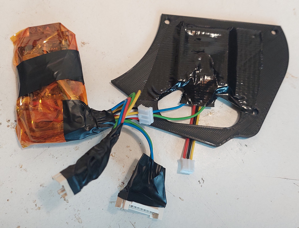
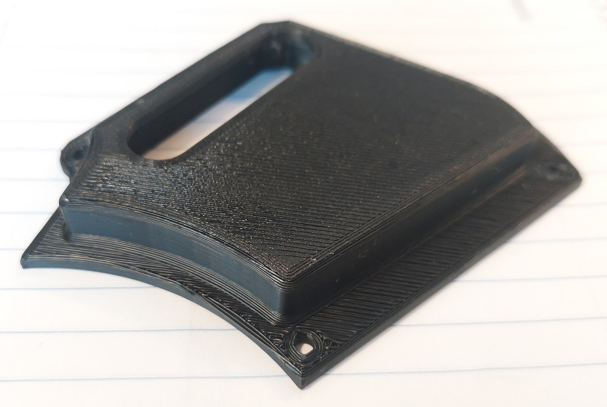
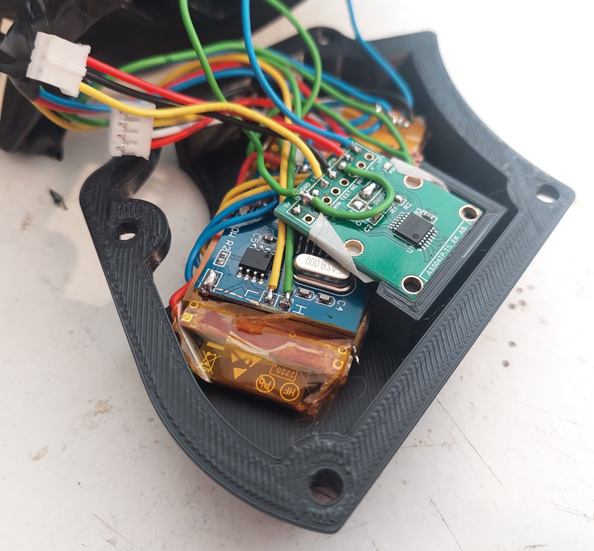
And here is the 3D printed cover, with the AS5047 magnetic encoder board in placed (I used thin double tape to glue the board):


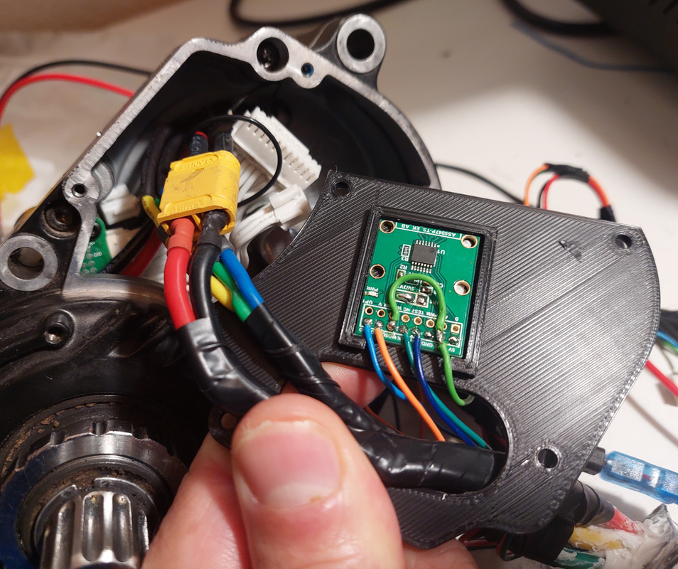
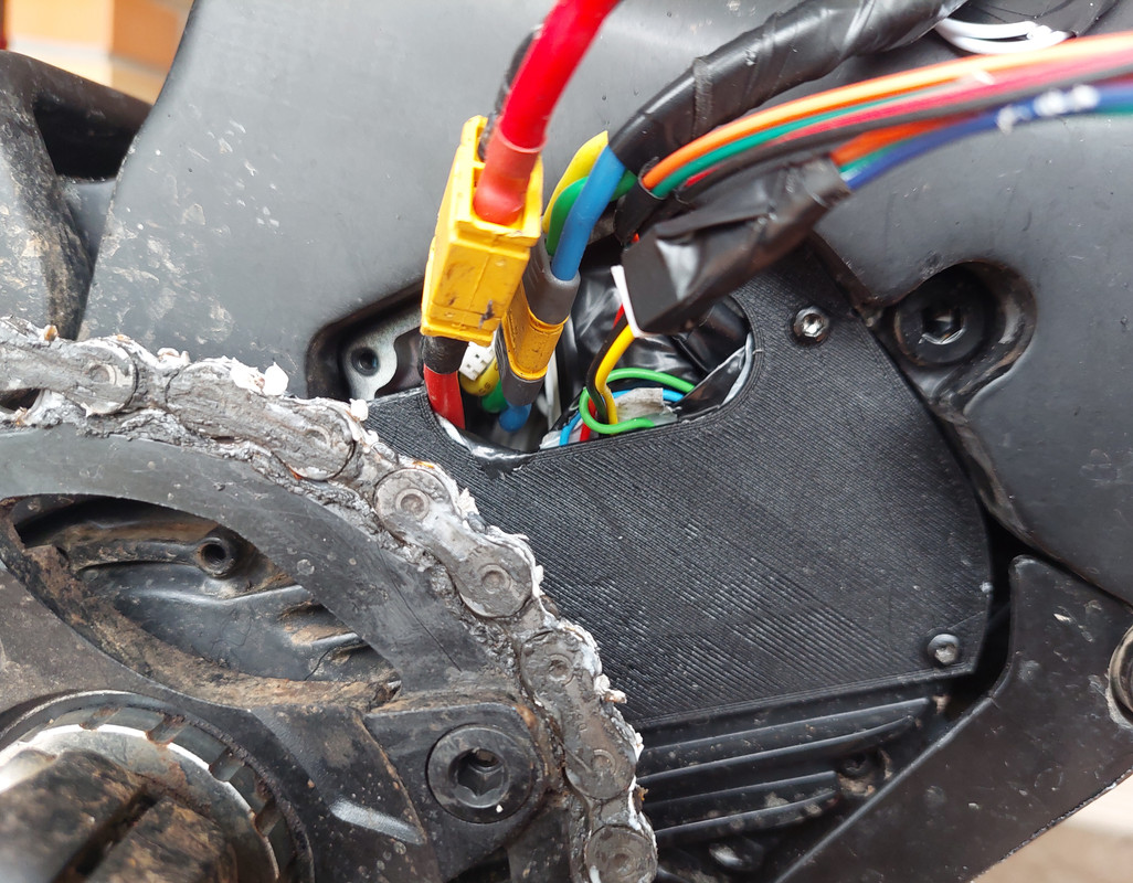
And here is the cover in place:


What were the results??

Testing on the VESC tool, I can see the magnetic encoder read angle relative to the motor rotor shaft, at the values seem perfect.

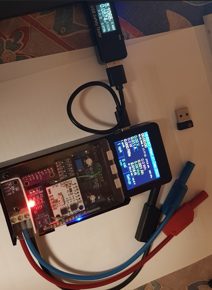
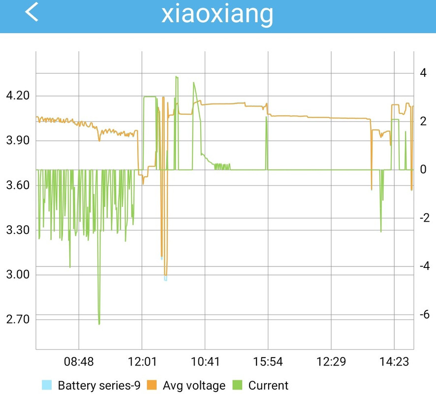
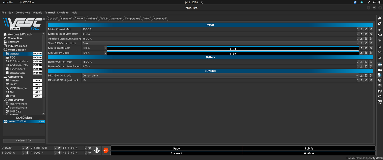
Seems to me the motor startup is good. I tested what was the minimum motor power for motor to be able to run, I used a constant duty-cycle on VESC tool, and I got a minimum of about 0.08 duty-cycle (8%) to keep the motor running and in this case it uses about 1W of power (1.5A of motor current, 0.35A of battery current, on a 30V battery voltage).

I expect to need a minimum of 25W of motor power, anything less will probably be to much lower. So, if motor can runs with a minimum 1W, that is great!!

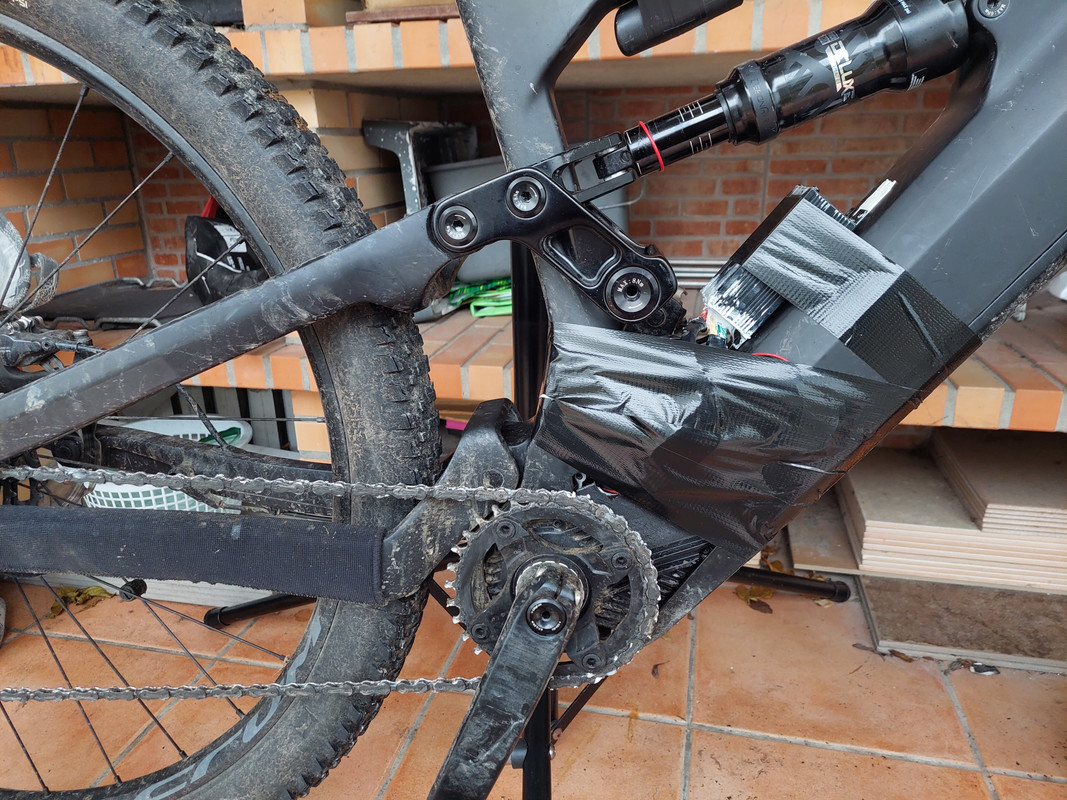
But next I need to install all this on my EBike and do the real tests. Let's see how it will go!!

Here is a video of VESC tool showing the motor running at max power it draws, on my bench, without any load. I also tested the min power needed for it run. Also we can see the read angle from the AS5047 magnetic encoder board: https://www.youtube.com/watch?v=OC0KvdqMl58

[youtube]OC0KvdqMl58[/youtube]
 
Caisanho, phew that looks to be a lot of detective and electronics work going on there.

On the printed cover, is there a possibility of stepping out that cover to create a larger void inside the motor, even 5 - 10mm maybe enough to get a full Mini VESC setup in there.

Good luck with the actual real time trials on your bike.

Also, the way my M500 respond to the pedal, I am pretty sure original firmware do not use the cadence, only the torque to then define the motor current.
I'm not sure but I think my M600 reads the torque at low rpm and then seems to get to a cadence rpm point where it switches to almost cadence based output.
 
 
Waynemarlow said:
On the printed cover, is there a possibility of stepping out that cover to create a larger void inside the motor, even 5 - 10mm maybe enough to get a full Mini VESC setup in there.
I have bad news about this. I found difficult even to put inside current EBike board, because all the wires and connectors. I even considered to mode the EBike board to outside, to near the VESC. As on next days I will be installing everything on my EBike, let's see the best I can do.

Anyway, I need my EBike ready for a potential day of riding on day 15 January, with probably rainy and a lot of mud, so my priority is to get the EBike fully ready and water prof -- no water should be able to enter the motor!!

On this iteration, I will keep using the Flipsky 75100. On next iteration, let's see. What I think is bad on 75100 is the need to remove the hall sensor filters, which was hard to do!! I should look for a controller that is also easy to remove them or if possible, that there is no need to do it.
 
It feels perfect!!

Finally I got the EBike board installed on my EBike and using the AS5047 magnetic encoder board to detect the motor rotor position, just like the original motor controller does. See here how it behaves with me pedaling with hand: https://www.youtube.com/watch?v=EL9Jek3_hDg

[youtube]EL9Jek3_hDg[/youtube]

It is raining and so I can not test it very well but I did some very short rides and it feels very good. But you can also check the startup noise I had here when using sensorless / not using the AS5047 board - listen the startup noise of motor gears at begin of the video: https://www.youtube.com/watch?v=Xki6n73GpXk

Assist level

On the current state, I only have the torque sensor and brakes sensors connected, I am missing the display. Still, as I can quickly edit the Python code on my phone, created the variable "assist_level_factor" where I can set a value like 1.0, 0.5, 3.0 or such (see next screenshot from my phone). This value simple multiplies the torque sensor value, that will be mapped linearly to the motor current / motor torque, like: 10kgs on torque sensor will set 10Amps of motor current, and 20kgs on torque sensor will set 20Amps of motor current.
And as you can see, I can also quickly tune some parameters as motor max current, torque sensor min value, etc:


So, this is my final EBike board + the 3D printed motor cover with the AS5047 board (behind the black tape):


But I found hard to put all inside... I had to cut part of the cover otherwise I would not be able:


And here is the final result, not water prof for sure :lol:


And for the curious to learn, here is the main EBike code, that I consider almost finished and easy to understand:

 
Great achievement! Glad to see torque to motor current is working well.
As you don't have any "PAS active" perimeters it seems the motor starts from standstill?
How does is behave at very low cadence? Do you feel to much motor torque sometimes?
How is the overrun on the other side ?
I am not the best coding but had experience in improving torque based systems, basically on analog solutions easy to convert into digital i believe. So below is my proposal :

From the very low motor efficiency at low speed it would be good to introduce dynamic torque offset at 0-20% of usable motor RPM. Looking again on motor simulator it seems that below 20% of motor speed the efficiency drop well from 40% to 0%. Thus it generates a lot of heat and not much forward motion ;)
For my hub ebike i am using this torque offset apart from regular torque control and it works quite well with little more energy consumptions.:

1. So the idea is: the closer to 0RPM the more torque offset is introduced: (at startup let human being to generate starting torque with little help of motor only if required.)
the max torque offset is ideally the weight of single leg :) for me this is close to 20% of my body weight.
2. The offset shall be gradually reduced to 0 @ 20% of max motor RPM.
2022-12-28 18_19_31-Moment i Moc - V5 offset.png
so like @ 0RPM the torque read would be that green line,
@ 20% of max RPM would be that yellow line.
3. It can be accomplished by the formula:
if rpm < 20% then:
Torque = Torque - max torque offset(20%-rpm[in % value])/20%
 
szkuba said:
Great achievement! Glad to see torque to motor current is working well.
As you don't have any "PAS active" perimeters it seems the motor starts from standstill?
How does is behave at very low cadence? Do you feel to much motor torque sometimes?
How is the overrun on the other side ?
I am not the best coding but had experience in improving torque based systems, basically on analog solutions easy to convert into digital i believe. So below is my proposal :
For now, motor starts as soon as I press the pedal, but only after a min of 4kgs of weight - that is about the value of my leg when resting on the pedal.

Today I was looking at the values of torque sensor and seems the lowest value of candence is about 15 rpm. Also, seems that at least, one good value is sent every one second.
With this, I think is ok to use candence for pedal human power calculation.

The torque value seems to have good sensitivity and be fast enough to be the only one used to detect the start and stop of pedaling. Like, I can be rotating pedals fast but not doing almost any torque, so on this case the motor simple stops, as my pedal human power is very near 0 value.

I like the boost / peak I get at startup on the original firmware, and I would like to replicate it.

Then, after that peak, I wish to follow the graph I already shared, where there is a min constant motor power like 50 or 75W while I pedal at a vslue lower than 200W of my pedal power, and only after that, the motor power will scale, probably square function.
The idea is that I use the EBike as a regular bike up to a bit lower value of my FTP, only after that, I want that motor assists me, so this way I will be forced to keep my effort and so boost my fitness.

And I tried today to ride but my BMS is cutting the power after like 5 or 8 battery amps. My BMS logs the battery voltage and current, and as this did happen to me in the past several times, the battery voltage is suddenly dropping, as seen on the log graph of the BMS!!
I am pretty sure this is because the battery got watter inside... Unfortunately, this Dengfu frames are not water resistant and water and easily go inside.

So my main priority now is to repair my battery.

Valuable BMS log graph showing the voltage suddenly drops:
 
Another developer is doing the same but for TSDZ2. And what is interesting is that he found the Flipsky mini has a volume good to fit inside the case of the original motor controller!!! See next image.

I already bought the Flipsky mini fsesc6.7, but it may take 2 weeks to arrive.

Flipsky mini inside TSDZ2 original motor enclosure:
 
casainho said:
...
For now, motor starts as soon as I press the pedal, but only after a min of 4kgs of weight - that is about the value of my leg when resting on the pedal.

Today I was looking at the values of torque sensor and seems the lowest value of candence is about 15 rpm. Also, seems that at least, one good value is sent every one second.
With this, I think is ok to use candence for pedal human power calculation.

The torque value seems to have good sensitivity and be fast enough to be the only one used to detect the start and stop of pedaling. Like, I can be rotating pedals fast but not doing almost any torque, so on this case the motor simple stops, as my pedal human power is very near 0 value.

I like the boost / peak I get at startup on the original firmware, and I would like to replicate it
....
So the cadence should not be a big problem starting to read from value 15 but the 1sec reading interval seems to big, those when taken into calculation it can result in jerky operation.
I did not had a chance to ride original Bafang setup hovewer i heard that it is a bit to sharp despite lowest level being to strong. Did you had a chance to ride Shimano EP8 or Yamaha PX-2 or Brose motor on technical uphill trails? Those also have startup assist although defined on different level. For me Yamaha start is strongest (even to strong sometimes) Shimano is in the middle and Brose have the softer start assist. Depending on application this can be either the benefit or a problem. So on flats it is OK but on slippery terrain can be a problem. I was riding Yamaha in the mountain trails and on some technical uphills can be to strong resulting in wheel slip, though Brose have this defined best in my opinion. BTW for the fitness it is better to not have strong start boost , that is my personal view of course ;)
Anyways is your current setup having any overrun? On the video it seems not a big overrun if any, but like to see you opinion from the rides you did, so if it helps to go through pedal dead spot?
 
szkuba said:
BTW for the fitness it is better to not have strong start boost , that is my personal view of course ;)
Anyways is your current setup having any overrun? On the video it seems not a big overrun if any, but like to see you opinion from the rides you did, so if it helps to go through pedal dead spot?
I never tested other motors, only TSDZ2 and this Bafang M500.

The overrun / delay to stop motor: the torque sensor seems to be fast to measure, with almost no delay. Then, the only delay can be from the EBike app processing + sending the command to VESC. And the VESC itself is fast to control the motor.
On current EBike firmware, the delay to stop the motor can be lower or faster than with the original firmware - at least I found I could have the delay smaller than the one original firmware has. To configure the delay, we need to configure the current ramp down value - currently I am using 0.05 seconds, which is the time it takes to reduce each 1A, so if actual motor current is 20A (almost the max of M500), it will take 1 second to stop -- here the code:


But anyway, the code is so simple to understand (this can be improved!), anyone should be able to change the simple math equations for what he likes - change them in real time using his phone. So I do not care to much at current project phase. I hope you can build your system and try it by yourself and give your feedback.
 
Previously I were trying to test ride my EBike but I had the issue that battery power were cutting and I thought it was because some issues with my battery. Turns out the issue were with an incorrect configuration of VESC I did.

Now with the problem solved, the system works perfectly. I think it works at least as well as original motor controller and firmware. The big advantages compared to original motor controller is that I have FULL control of the motor and full control of the firmware!!

On my tests I even found the magnetic encoder sensor is not really needed as VESC sensorless algorithm works very well. But using the magnetic encoder sensor, gives the best startup torque possible.

My EBike is mostly ready to use!! Still is missing the wheel speed sensor, the motor temperature sensor and the display - will be my next steps.

I am also trying to improve the motor cover and hide the best possible all wires, and make everything water prof:

 
Can you share more details what was improved and stopped battery cutting off?

secondly
casainho said:
..
I never tested other motors, only TSDZ2 and this Bafang M500.

The overrun / delay to stop motor: the torque sensor seems to be fast to measure, with almost no delay. Then, the only delay can be from the EBike app processing + sending the command to VESC. And the VESC itself is fast to control the motor.
On current EBike firmware, the delay to stop the motor can be lower or faster than with the original firmware - at least I found I could have the delay smaller than the one original firmware has. To configure the delay, we need to configure the current ramp down value - currently I am using 0.05 seconds, which is the time it takes to reduce each 1A, so if actual motor current is 20A (almost the max of M500), it will take 1 second to stop -- here the code:


But anyway, the code is so simple to understand (this can be improved!), anyone should be able to change the simple math equations for what he likes - change them in real time using his phone. So I do not care to much at current project phase. I hope you can build your system and try it by yourself and give your feedback.

Looks very promising, great achievement :) i wish someone could do side by side comparison of the original and OSF systems.
 
szkuba said:
Can you share more details what was improved and stopped battery cutting off?
Two issues:

1. Magnetic encoder high speed limitation: after some high speed, the encoder always fails. The solution were to reduce the Sensorless ERPM to a value before the limitation of the magnetic encoder. In the end I decided to reduce to the very low value of 1000:


2. To low motor current limit and/or disable Slow ABS current limit: The EBike application was setting a motor current from 0 to 20A but the VESC motor current limit was equal, so probably VESC was cutting abruptly (solution: increase limit on VESC to 30A). Also, the Slow ABS current limit was disabled:


szkuba said:
Looks very promising, great achievement :) i wish someone could do side by side comparison of the original and OSF systems.
That is impossible, as there are parameters that we do not know on the original firmware. With our OpenSource system, we will always get more power, because the manufacturer put some moderate limits. Like we can for sure use higher motor current to get more motor torque, but that may increase the gears wear.
 
So I decided to remove the chainring so this way will be easier to install the EBike board and also add the silicone to make everything water prof:


And make easier, I decided to keep the EBike board on the 3D printed cover, just under the magnetic encoder board. This way I will be able to assembly everything previously and then just need to connect the connectors:


As this EBike board with ESP32 have a CAN controller, I will try to use instead a smaller board and not the one I am being using that needs SPI communication. The advantage will be less wires needed.

And as I need to test, I decided to make a specific Python file just to test the torque sensor, so it will help me to understand if the wiring are correct. This testing firmware will be part of the firmware folder, so at anytime, the user can use it with his phone to check the hardware -- mainly when assembling the board and doing the initial tests:

 
CiDi said:
To configure the Bafang M500 / M600 motor without using the BESST programmer, you can use this interface.

Link interface USB to CAN on Amazon:
https://www.amazon.co.uk/USB-Converter-Module-Raspberry-Zero/dp/B07Q812QK8/ref=sr_1_2?dchild=1&keywords=usb+to+can+innomaker&qid=1604409709&sr=8-2

Link cables Bafang HMI M500/M600 on e-bike-technologies:
https://www.e-bike-technologies.de/index.php/en/connectors/connectors-signal/connectors-higo-mini-f-series/higo-b5-f-detail
https://www.e-bike-technologies.de/index.php/en/connectors/connectors-signal/connectors-higo-mini-f-series/higo-s5-f-detail

Below are the software and the instructions for configuration and use.

Someone knows how to calibrate motor with canbus code sent by CiDi ?
there is 2 frame id , torque and position sensor calibration ..?
it's usefull after motor and controler replacement / update ?
 
Back
Top