Bafang M500/M600 thread

Waynemarlow said:
The outer cover to the motor, could we not get a CNC'd aluminium cover made. ...

Certainly a possibility. I'm not sure where the economics work out best.... Use an existing mass produced (cheap) board and a custom (somewhat expensive) heat sink, or develop our own medium production board (likely a bit more than the cheap board), but which could use the OEM heat sink (no additional cost)
 
I showed that the OEM heat sink fits the "cheap" mass-produced board.

It is easier / faster / cheaper (one evening with a beer) to do a project of a new cooling on the CNC than to develop individual electronics that may not work properly.
 
I see where that board does fit inside the OEM space. Though not sure I see where the heat sinks line up? The OEM heat sink has a fairly unique arrangement of thermal pads inside. Though possibly it is 'close enough' or could be adapted. I don't think modern mosfets are generating a lot of heat, but do need some cooling.

M500-M600 board outline and locations w-pads.jpg
 
The OEM heat sink has a fairly unique arrangement of thermal pads inside. Though possibly it is 'close enough' or could be adapted.

It doesn't matter where the old thermal pads are. The OEM plate is made of aluminum and the heat is transferred to each place using the appropriate thickness of the thermocouple.
We want to take about 11A for the M500 (48V * 11A = ~ 500W) and about 20A for the M600 (1000W). This is little for these mosfets, it is possible to obtain 70A continuous current with a standard heat sink.
 

Attachments

  • 10.jpg
    10.jpg
    297.8 KB · Views: 440
About HFI silent, I see 2 disadvantages:
1. Narrow list of controllers: reduces the potential to find a controller that can be installed inside the motor.
2. Less efficient: I did read HFI uses battery energy to generate extra current pulses. I do not now how much energy is wasted but I need to save battery weight and size, so I would prefer to avoid HFI if manageable.

Since we found a controller that can be installed inside the motor, I would prefer to use that one. And if a group of people can buy and offer it to me, I would really appreciate as I am short in money, since I already invested a lot in parts for this project.

And if the controller can be installed inside the motor, then I would prefer to try use the encoder board. With that, we know we will have the best torque possible at startup including efficiency. As also we should be able to use any VESC version, no more limits about HFI silent.

Meanwhile, I just found in stock an encoder board (that round small, black board), from other project I never finished. This means I can test the motor with this encoder, and this cheap VESC controller I have. The only think I miss is that VESC controller that is small. And this assuming I will not burn one of this pieces during the development :wink:


There is a lot of work on the table, if I will be doing it alone, It will be slow. Is there anyone available to help in like testing the encoder board? would need to design and 3D print a cover to keep the board in place - similar idea as done here:


And there is a big issue with this small controllers, that is the battery voltage. Seems the smaller and "older ones" are recommend only up to 12S batteries - Flipsky product site says explicity:

"Voltage: 14V-60V(Cells: 4-13S; safe for 4S to 12S, voltage spikes may not exceed 60V! )"

So, the standard 48V are 13S and not 12S.

Seems Bafang M500 and M600 are 36V motor, but can hold higher voltages up to 52V batteries. While I can do my own batteries of 11 or 12S, is more difficult to find and charger and BMS for that voltages. Even very hard to find a battery to buy for our frames that is not 48V or 36V.

So, what should we do?

At least the "big" Flipsky 75100 is rated for 75V, but that will not fit inside the motor...
 
Bit off-topic, but have anyone seen any adapters for M500/M600 mount on Bosch Gen2 bikes?, My scott e-bike has burnt motor and stock motors is hard to find. Would be an option to attach an M500/600 instead
 
casainho said:
And there is a big issue with this small controllers, that is the battery voltage. Seems the smaller and "older ones" are recommend only up to 12S batteries - Flipsky product site says explicity:

"Voltage: 14V-60V(Cells: 4-13S; safe for 4S to 12S, voltage spikes may not exceed 60V! )"

So, the standard 48V are 13S and not 12S.

Seems Bafang M500 and M600 are 36V motor, but can hold higher voltages up to 52V batteries. While I can do my own batteries of 11 or 12S, is more difficult to find and charger and BMS for that voltages. Even very hard to find a battery to buy for our frames that is not 48V or 36V.

So, what should we do?

At least the "big" Flipsky 75100 is rated for 75V, but that will not fit inside the motor...

On the voltage, I think older nominal battery voltages of 36 and 48V are fairly common. There seem to be a lot of electronic components where 60V is a nominal step. The problem starts to come in with a fully charged 14S battery being ~58 to 59V, which is really pushing a 60V limit, especially considering any spikes.

Ideally, I think it is better to make your motor power with higher voltages as that means less current (V x I = W), so less I^2R losses in the wires and windings overall.

Of course the complicating factor is that a lot of mosfet gate drive chips I see are "60V" max so that makes somewhat of a natural limit, or means running three (technically 4) power rails on the board.... Battery voltage, 15V mosfet gate drive, 5V peripheral power and 3.3V MCU power.

I'd have to look at the big flipsky - is it big because it needs 3 power rails, or some other reason? Capacitors also get bigger with higher voltage for the same capacitance, but this is relatively minor at the levels we need. OEM Bafang did squeeze three power rails on the board, so should still be possible. Plus if flipsky can run sensorless, we can eliminate the mag sensor and associated components which frees up some space. I also did some searching and found an Infineon BSC040N10NS5SCATMA1 mosfet which is 100V, 136A @ 4mOhms resistance. This mosfet looks to be in good supply and should cover most any use in these motors as a single mosfet, so no need to 'double up' as the OEM bafang M600 did.
 
The present M600 controller is rated to only 48 volt 13S batteries but so many run them on 14S batteries without failures that I would have to suggest that the 58.7 volts full charge on 14S still has enough voltage clearance as to push forward with the smaller 60 volt modules. My batteries float charge to 58.7 Volts but almost immediately drops back to under 58volts on first use. Can we not fit a 60 volt over voltage limiting diode into the circuit to protect the VESC module ?

We may have to compromise long term reliability ( which I doubt ) perhaps for those using 14S batteries to enable a module small enough to go inside the motor, wiring outside the motor is just looking for unreliability. My instinct is to chance a 60 V VESC module that can handle the later versions of VESC over increasing the size.

Casainho I think it’s best for delivery purposes that we simply send you funds by a PayPal account ? If those wanting to contribute some funds to you, if we PM you, could you respond with your PayPal account perhaps.

If perhaps you were to continue using the older VESC unit for say a couple of weeks, perhaps another thread contributor may come up with another more suitable module but I have to say on first look the FLIPSKY Mini FSESC6.7 PRO 70A seems to tick a lot of boxes.
 
Sorry to barge in the topic a bit widely but two things need to be mentioned:
-Flipsky is not a company very famous for it's marketing claim fairness and ethical behaviour.
-The biggest issue with the 6.7 mini is that vesc are VERY sensitive to voltage spikes (like really really :) ) a 60V advertised vesc is good for 12s. not 13... So this controller will be good for this not more :)
Also most of this surface mount mosfet controller use toll format and not tollt which reduce immensely the cooling possibilities. the 75100 for example, if mounted on a good cooling is really able to deliver 80A(160 peak) phase quite stable and if a fet blows... well to220 is easy to replace. and yes toll format reach easily 400W-1.2mOhm and that's great (see the 75100 V2 alu version) but again, we are diy guys, and having a controller difficult to repair is something we should take in consideration :)
the 75100 isn't perfect, design issues with shunts, absolutely useless "heatsink" and dancing capacitors...
Happy to see the ES finally jumping on the vesc... and wait for the new update (v6) some pretty badass things are coming in <3
love from Germany,
Hadrien
 
The biggest issue with the 6.7 mini is that vesc are VERY sensitive to voltage spikes (like really really :) ) a 60V advertised vesc is good for 12s. not 13... So this controller will be good for this not more :)

For what reason should the pressure spikes happen? In a bicycle with a central drive, we do not use recuperation and the maximum engine revolutions are rare. No sudden stops or engine braking. What are the voltage spikes? More theory than practice. If we don't try, we won't know if this board can handle it.

https://lunacycle.com/blog/luna-m600-ludicrous-v2/

Give the source where people are complaining about problems with this board mini.

Also most of this surface mount mosfet controller use toll format and not tollt which reduce immensely the cooling possibilities.

We need max 20 Amps from the controller which is specified at 70 Amps. Will there be temperature issues?

and wait for the new update (v6) some pretty badass things are coming in

The latest version of the mini board is based on the VESC 6 mk6.

Maybe get inspired by Luna and make a new board.
https://lunacycle.com/blog/luna-m600-ludicrous-v2/
 
I am being reading opinions from different users, here and on 2 telegram channels (that's for everyone!!). Everyone almost do not recommend to use 13S, but 12S.

On my test to run the motor with the throttle, as you can see, I setup a motor current from 0 up to 5A and a 0 amps brake current. That is because I am running from a lab power supply and If VESC would use a brake / regen current, the voltage of my lab power supply would increase and would risk to damage it (that already did happen to me in the past). But also the VESC could burn, because this (and cheap) lab power supply are not batteries and they do not limit voltage and returning current!! An high voltage because of the motor, could both damage the lab power supply and the VESC.
My lab power supply outputs max of 32V and the VESC is max 60V.


You can check here in the video, that the lab power supply never goes over 30V:

[youtube]QEnLWcn1LbE[/youtube]

So I would risk to try use this 60V VESCs on our project. I think there are mainly 2 reasons that we are safe:

- VESC brake current needs to be set to 0: this works for our EBike application, as this motors do not need to brake and so they will not produce any regen!! (otherwise that would be a BIG marketing point, a mid drive motor that also charges the battery on down hills).

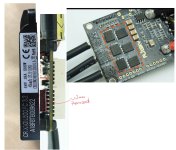
- Freewheel: I think this mid drive motors freewheels, as seen on the video, it does not rotate backwards, so I think they will not provide any big currents that can increase the battery voltage

-----

For my development, I only have that controller from the video and I hope to receive next week the Flipsky 75100. But if some of you would like to contribute for me to buy that smaller controller (my Paypal is in my signature), I will do it and start using it.

@rezystor1990, you did a great work showing that is possible to put this small VESC controller inside the original motor. Can you help further in like design and 3D print the part to hold the encoder board + the VESC?

NOTE: we are using the Telegram for a faster communication for development, everyone is free to join: https://t.me/bafang_m500_m600_development
 
I checked carefully my connections to the torque sensor. As we can see from the lab power supply, it uses near 10mA @5V, that is 0.05Wh. So, 1.2W a day, 36W a month. So the torque sensor alone will discharge 10% of my battery in a month. This means we will need a way to turn off the EBike board (and VESC ??) as most as possible. For initial phase, I can use the button on my Dengfu E10 frame the turns off my BMS output. But ideally, the system should power off itself after some timeout of not being used, like after 1 our 4 hours (assuming the user forgot to turn off the EBike on the display, my wife does this a lot):


The full board as it is actual, with throttle connected as also the torque sensor, with the VESC, uses near 0.1Wh, so 72Wh in 1 month.
 
Waynemarlow said:
Should the battery BMS not turn off the battery if it gets below the bottom voltage threshold.

Funds sent.
The idea is that the battery does not discharge while the EBike is turned off, so we do not need to charge it just before we will ride it.
And is bad for batteries to fully discharged, so we should avoid them to go up to that so lowest value of BMS low voltage cut value.

Thanks for the donation.
 
casainho said:
Thanks for the donation.
We should all be appreciative of the work you have put in on both this project and the TSDZ2 project and of course also to all the others that contribute behind the scenes, to better EBiking with our Bafang motors.

In regards to the short term, most of us here are regular riders and will look after our batteries, both using and charging often. At this stage an external turn off / on may not be so necessary.
 
Waynemarlow said:
casainho said:
Thanks for the donation.
We should all be appreciative of the work you have put in on both this project and the TSDZ2 project and of course also to all the others that contribute behind the scenes, to better EBiking with our Bafang motors.

In regards to the short term, most of us here are regular riders and will look after our batteries, both using and charging often. At this stage an external turn off / on may not be so necessary.
I agree, it is not a priority on the project to have it optimized for low power usage.

I need to write a list of important things / ideas for future implementation, and this one should go there.

Today I tried to read the torque sensor, but seems the issue I am having is because the Python drivers for MCP2515 are for Adafruit boards that uses a 16MHz xtal on MCP2515, while the cheap chinese module I am using uses a 8MHz xtal. I am now trying to change the drivers is a way to accept both 16 or 8MHz, and then submit a pull request to this drivers, in the hope Adafuit will accept this contribution and also make life easier for future users of this cheap modules (that includes the users of this project).
 
casainho said:
I checked carefully my connections to the torque sensor. As we can see from the lab power supply, it uses near 10mA @5V, that is 0.05Wh. So, 1.2W a day, 36W a month. So the torque sensor alone will discharge 10% of my battery in a month. This means we will need a way to turn off the EBike board (and VESC ??) as most as possible. For initial phase, I can use the button on my Dengfu E10 frame the turns off my BMS output. But ideally, the system should power off itself after some timeout of not being used, like after 1 our 4 hours (assuming the user forgot to turn off the EBike on the display, my wife does this a lot):


The full board as it is actual, with throttle connected as also the torque sensor, with the VESC, uses near 0.1Wh, so 72Wh in 1 month.

I don't know that it is really practical to turn the entire board off. You'd either need big mosfets or relays to handle the entire expected battery voltage/current. Plus, somewhere the board needs to 'wake up', which means always scanning for a button press or similar. Though might be possible to run a couple small mosfets to shut down unneeded peripherals. Though, really, 10% per month is not that bad! Who leaves a bike turned on, but doesn't ride for 10 months?!?! lol :D
 
4πr^2 said:
casainho said:
I checked carefully my connections to the torque sensor. As we can see from the lab power supply, it uses near 10mA @5V, that is 0.05Wh. So, 1.2W a day, 36W a month. So the torque sensor alone will discharge 10% of my battery in a month. This means we will need a way to turn off the EBike board (and VESC ??) as most as possible. For initial phase, I can use the button on my Dengfu E10 frame the turns off my BMS output. But ideally, the system should power off itself after some timeout of not being used, like after 1 our 4 hours (assuming the user forgot to turn off the EBike on the display, my wife does this a lot):


The full board as it is actual, with throttle connected as also the torque sensor, with the VESC, uses near 0.1Wh, so 72Wh in 1 month.

I don't know that it is really practical to turn the entire board off. You'd either need big mosfets or relays to handle the entire expected battery voltage/current. Plus, somewhere the board needs to 'wake up', which means always scanning for a button press or similar. Though might be possible to run a couple small mosfets to shut down unneeded peripherals. Though, really, 10% per month is not that bad! Who leaves a bike turned on, but doesn't ride for 10 months?!?! lol :D
TSDZ2 and Xiaomi M365 motor controllers, that I am aware of the schematics, do turn off, they enter low power mode. I think that is the ON/OFF display button that do it.

For a DIY board, I understand we need to be minimalist but for a controller as the one you are designing, I would say it is a must for the microcontroller to be able to turn off the board and turn on with display ON/OFF button.
 
Seems Genuine VESC's from Trampaboards support hibernation (per website consumes less than battery self discharge), but I have never tried it.
 
Yes - looking at some of the latest schematics, it seems they do have the ability to shut down the 5V power rail, so that would eliminate consumption from a lot of peripherals... bluetooth, torque sensor, temp sensors, etc.
 
4πr^2 said:
Yes - looking at some of the latest schematics, it seems they do have the ability to shut down the 5V power rail, so that would eliminate consumption from a lot of peripherals... bluetooth, torque sensor, temp sensors, etc.

It might not only the power rails being shut down, the processor F405 has low power modes (drawing very less current) from which it can wake up in response to external triggers.
 
afzal said:
4πr^2 said:
Yes - looking at some of the latest schematics, it seems they do have the ability to shut down the 5V power rail, so that would eliminate consumption from a lot of peripherals... bluetooth, torque sensor, temp sensors, etc.

It might not only the power rails being shut down, the processor F405 has low power modes (drawing very less current) from which it can wake up in response to external triggers.
Or as on other controllers, the 5V is turned off and so also the microcontroler will be off. But ON OFF dispaly button will switch on again the 5V and so everything will restart from fresh -- very good to avoid any possible firmware lock bug.
 
rezystor1990 said:
The biggest issue with the 6.7 mini is that vesc are VERY sensitive to voltage spikes (like really really :) ) a 60V advertised vesc is good for 12s. not 13... So this controller will be good for this not more :)

For what reason should the pressure spikes happen? In a bicycle with a central drive, we do not use recuperation and the maximum engine revolutions are rare. No sudden stops or engine braking. What are the voltage spikes? More theory than practice. If we don't try, we won't know if this board can handle it.

https://lunacycle.com/blog/luna-m600-ludicrous-v2/

Give the source where people are complaining about problems with this board mini.

Also most of this surface mount mosfet controller use toll format and not tollt which reduce immensely the cooling possibilities.

We need max 20 Amps from the controller which is specified at 70 Amps. Will there be temperature issues?

and wait for the new update (v6) some pretty badass things are coming in

The latest version of the mini board is based on the VESC 6 mk6.

Maybe get inspired by Luna and make a new board.
https://lunacycle.com/blog/luna-m600-ludicrous-v2/

Hey, the vesc isn't sensible to "slow" voltage rises, but to "spikes". they happen when you plug the battery in for example, or when the back emf, for some reason cannot find a consistent load. Trust me there, 60V-able drv were the biggest brake to vesc-for ebikes :)

Concerning the current and heat dissipation. I don't think the motor takes only 20A... you mean phase current right? the phase current is what makes mosfets warm, specially at high foc refresh frequency and slow commutation (slow erpm).

BUT one thing is great with vesc. you want to use the mini? do it :) there will be close to no difference on the programming side, you will just have your mini-flavour f the m500-vesc :))
 
dodjob said:
Hey, the vesc isn't sensible to "slow" voltage rises, but to "spikes". they happen when you plug the battery in for example, or when the back emf, for some reason cannot find a consistent load. Trust me there, 60V-able drv were the biggest brake to vesc-for ebikes :)

Concerning the current and heat dissipation. I don't think the motor takes only 20A... you mean phase current right? the phase current is what makes mosfets warm, specially at high foc refresh frequency and slow commutation (slow erpm).

BUT one thing is great with vesc. you want to use the mini? do it :) there will be close to no difference on the programming side, you will just have your mini-flavour f the m500-vesc :))
Yes, I never looked at VESC because of this voltage limitations. My EBikes were always 48V / 13S.

For that 2 examples of voltages spikes, I think we will need to write on the instructions some suggestions:

1. Plug the battery spike: use Amass XT90 connector that has integrated resistor for slow charge of motor controller capacitors. In fact I just bought them but I never used them, but looking at reviews from users, seems they are a no brain choice. See the picture bellow of Amass XT90:

2. Back emf / regen voltage spike: as I already explained, since this motor freewheels, I think we take the risk although explaining to users to avoid rotating the motor with the battery power unconnected.

Good question about the motor phase. I think no one knows what is that value on the original firmware. My guess is that motor will handle at least twice of the battery current, so for my M500 (36V motor) of 500W, 24A battery current and 48A motor phase current.

My plan now is to buy the mini vesc at some point. For development, I have the current one Flipsky 4.2 as also I will receive today the Flipsky 75100. I do not mind to start by using a big one for doing the initial tests and development.

On the development, I am currently blocked because the Adafruit CircuitPython drivers for the MCP2515 do not work for this board, I am still trying to make it working.

 
Back
Top