DanGT86
100 kW
I ended up with a free 98 honda cr125 frame i've been wanting to convert and found out its so stiff everyone hated them when it was new. Im sure they have come a long way in the last few decades.
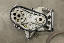
Hi,Yes there will be another gusset between the two to make it stronger. The shaft is th one from my previous build. It is made from a snowmobile shaft that happen to be the same spline as a ktm sprocket. I will bu using the same part but it will be a new one because it needs to be longer.
Think I just found a matching one, the Polaris XC700 looks like it's the same spline patternHi,
do you have any details of what snowmobile the shaft was from?
I'm trying to track down something about 10" long that a KTM sprocket will fit on.
thanks
yes when I realized I had to start all over again for the case I stopped working on it for a while. I hope it is still strong enough!Excellent work! I know you have a lot of time in that battery case as that’s the second case you made right?
I’m in the same position, have to file down the frame in a few spots for battery clearance. I think as long as we don’t remove too much material, it doesn’t weaken the frame by that much. These Japanese aluminum frames are super strong!
I used skidoo one. any year from the 90s will work they are all the same. I do not know for polaris.Think I just found a matching one, the Polaris XC700 looks like it's the same spline pattern
Thanks,I used skidoo one. any year from the 90s will work they are all the same. I do not know for polaris.


That is what I tough too for the jerking but I redid the motor detection 4 times and it still does.I wonder why the BMS went bad..
that’s strange the motor is jerking and cutting out. It almost sounds like something non-battery related although somethings not right with the battery since it burned up the BMS. It almost sounds like the phase wires are not the right combination, just a thought. I truly hope you get this sorted out, my friend! I know this is got to be aggravating.
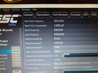
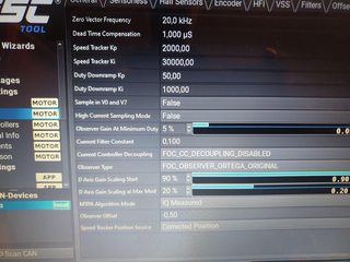
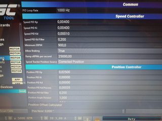
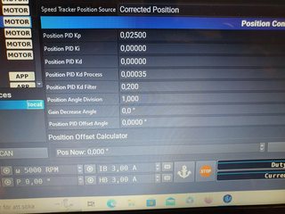
This is my first time using vesc, I only setted up an asi bac8000 before. here are my setting:Sounds like you have some problems with setting vesc up.
Maybe send some pics of what settings u have, maybe we can help. The jerking on startup sounds like ur running it sensorless mode. And check fualt codes.


Did you try the motor detection with the Android app or just the PC? Mine never worked properly with my laptop but did with the app.That is what I tough too for the jerking but I redid the motor detection 4 times and it still does.
Only with the pc. I can’t with the Bluetooth because mine is an early version and the Bluetooth module need to be plugged in but I can not find the wiring diagram of it.Did you try the motor detection with the Android app or just the PC? Mine never worked properly with my laptop but did with the app.
A few of these controllers have had communication issues with the PC connection.Running detection on the PC or app shouldn't make any difference but detection isn't always perfect and sometimes yields different results so running it a few times and averaging can help
I did the encoder detect but not sure if it is right or not.Running detection on the PC or app shouldn't make any difference but detection isn't always perfect and sometimes yields different results so running it a few times and averaging can help. That and make sure the detection current is roughly in line with your motor's size, so like running a very low detection current on such a large motor won't yield good results. If I recall you want like 10% of your target max current or something like that.
Also based on those screenshots the motor has an encoder so I believe there is an encoder detect that works the same way as the hall detect and is probably done along with the whole motor setup detection so rerunning the detection may sort that out if the encoder timing is off.
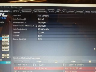
At first I did the motor detection like the 3shul video then the last few time I did it with the base vesc tool setting. I never get the same value exact value. I will try like scianiac said and do it wih 10% of max amp. Maybe there is a problem with the encoder setting.There are some differences between your numbers and mine. I have 2,8mohm resistance, 64,65uH inductance and 29,04uH in Ld-Lq difference. There are other differences too, I have some pictures I can post in the evening.
How do you do the motor detection? I havent used the choices on the start screen, I used other values from a you tube video from 3shul.
I previously followed this video by 3shul for motor detection.What current/power setting where you using for the previous detection modes? In my tuning I did the detection at a few different power levels and did see a bit of a trend of some values changing with higher detection current levels while some didn't much. And then if I recall I used the results from the higher test currents. I don't recall if 10% is the exact value I heard but you get the idea, using 1% of your target current is not going to get good results and same with 50% probably so you want something that can give the controller some real feedback but not a crazy amount.
Using the logging tools on the computer program also can help, I think there is a section that will show motor rotor angle so if you find that and spin the motor by hand you should see the position change nice and smooth from the encoder, same when running.
Also getting the bluetooth connected, helps a bunch because you can have the app running and when it cuts out you can see what the fault is and you can also data log tests. If it's a standard vesc style bluetooth module I think they all have the same wiring pinout.
Have you looked at the pin out in the manual?my problem with the bluetooth dongle is that there is no indication of what cable is what so I do not know what is rx tx 5v etc
yes I have the pinout from the controller. But the bluetooth dongle has no pinout to be found. just 4 wire comming out. Also I have the older version cl700 so it does not has the blug already made like in this manual. I shearched wih the bluetooth model number and still did not find pinout. the dongle is from 3shul.Have you looked at the pin out in the manual?
Did you look on the bluetooth module's circuit board, it looks like they are often labeled on the board itself. If not does it have a connector already on it, you can probably match that with the esc brand, looks like some use common pinout but not all.yes I have the pinout from the controller. But the bluetooth dongle has no pinout to be found. just 4 wire comming out. Also I have the older version cl700 so it does not has the blug already made like in this manual. I shearched wih the bluetooth model number and still did not find pinout. the dongle is from 3shul.