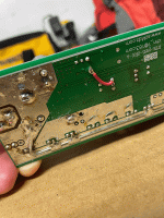
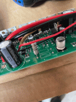
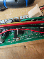
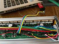
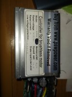
Got my STLink in the mail last week. Can confirm the $6 Aliexpress knockoff version works fine. Managed to fix my spare controller (actually my first KT 18 FET controller that came with the first kit I bought, a SVPR version that came with IRFB4110 FETs (4.2mA RDS on, very nice) from Pasionebike). Ran it successfully for a year of 48V/45A/2000W and 5000 hard, hilly kilometres. Started shutting off intermittently, usually after/during long hill and low pack voltage. Eventually it wouldn’t start up. Noticed the LM317 feeding the 7805 had no output. The big resistor that steps down battery voltage and feeds the LM317 gets hot and while looking at the board you could see a brown burn mark on the PCB where it goes in. Resistor tested fine but had high resistance in the trace at this leg going to the 317. Had to wire in a small ~1cm jumper wire from the bottom of the resistor to pin U2B feeding the 317 input. Controller works fine now. Originally thought it was the 7805 because I had no throttle voltage and controller wouldn’t boot up. Replaced the 7805 first, to no avail. Anyway.
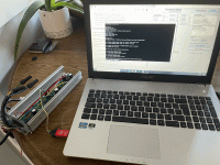
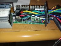
Soldered in a 4-pin header on the programming ports. I also have two other KT controllers, both 45A/18 FET 48/52V, one SVPR and one ZWS, both with Toshiba TK150E09NE FETs (not quite as exotic, but still good with 6.5mA RDS on). All have LSHC 63V 470uF capacitors on V+ battery, but the first controller came with only one (other location left blank). The other two have both spots populated with two caps. Between the two sine wave versions I also noticed different PCB revisions. My first controller put the ACS758 sideways on the B phase and the programming ports start with the 5V line on the opposite side (order reversed). This controller was purchased in 2019 from Pasionebike, PCB has 2016 stamped on it. The newer SVPR has 2018 stamped on the board, purchased in 2020 from Pasionebike. ZWS is from CSC, bought in 2021 as part of a 1500W kit. Newer controllers have slightly thicker phase wires as well. So now my spare sine wave controller is fixed and set up as my OSF test mule.
Used the 48V DD-12FET presets as a starting point. Left Cal A at 46, battery/phase current at 100/300, for ~22A draw on the battery to test around the 1000W level. Voltage calibrations were correct for 48V. Not using regen for now. Left throttle min/max at 43/182 (corresponds with .84V to 3.57V). Motor specific angle of 238 is perfect and same as the other 1500W DD “leafmotor” user. Didn’t notice a difference with the experimental anti-jitter on or off. I thought the factory sine wave controller was smooth and quiet compared to the ZWS. This is beyond what I expected — it’s eerily silent. Not even a slight hum of the factory SVPR program. More torque than before at 1000W at low speed. Top end is similar, which is what should be expected as duty cycle goes up and you have the same amount of current from the battery as before. Must be more phase amps at low speed than stock fw. Very nice.
I use throttle-only and like the “Throttle follows assist level” setting. Finally the assist level actually does something, and it’s nice to kick down to 100-300W to get the most range when cruising.
I had very slight oscillation at Gain I = 0.2, so after reading some posts here I set it to 0.1. I had a problem at first of the bike moving forward with no throttle input. You would start up the controller, it wouldn’t move, but as soon as you pushed the bike forward with no throttle input it would power forward (very weakly) a bit. After searching and reading this thread, I saw Stancecoke’s post about altering Cal B current initialization in adc.c code from -= 1 (slightly negative biased) to += 1 (slightly positive biased). This was in response to someone who thought the motor was dragging too much, but I had the opposite problem. At first, I tried going from -= 1 to += 1. Way worse, the bike would move as soon as it was turned on with no throttle input. Ended up trying Cal B -= 2 and that fixed it. Bike stays put when turned on/pushed forward.
From what I understand, adc.c deals with the analog-digital inputs of the microcontroller. In this case, we are looking at a value (Cal B) that offsets the PWM duty cycle that is constantly calculated when on (in response to throttle signal, among other things), right? Cal B offsets the calculated PWM duty cycle by a little bit to add/subtract so that the current at rest/no throttle input can be zeroed? Since the OSF does not shut off PWM at rest, is this even related to the throttle signal (and min/max) at all, and simply the right offset will let the bike rest without dragging or powering itself forward?
Is it coincidental that altering Cal B -= 1 to -= 2 fixed the problem and that I should be raising the throttle min? Would a throttle min setting too low cause a non-zero reading at startup?
Is the reason that the resting state/coasting/throttle response behavior are so different from the stock firmware because the OSF works in such a fundamentally different way? From what I gather so far: It uses an 8-bit sine wave lookup table to generate a sine wave current, indirectly. This is done by mapping each value 0-255 of the period of an 8-bit sine wave to a voltage (0-255) with a corresponding MOSFET PWM duty cycle (again 0-255 is 0-100% with 8 bits). Perhaps you just store a quarter of the period as a table to get a higher-resolution wave using 256 unique values with 8-bits, and you do sign operations and add/subtract to get the full period. Likewise, you only need to store one wave in a lookup table to save memory, and can generate three identical waves 120 degrees apart from this single one for the other two phases. Is it true that you do this calculation on a single phase for saving CPU time (it's a 16MHz 8-bit processor), but then add/subtract to get the other phases, and it goes through this loop every single PWM cycle (at ~16KHz PWM frequency, so you have <1000 cycles to do this for a 16MHz processor), right? So it's doing this constantly, whether accelerating, coasting, or at rest, and the outer control loops are making sure that battery current max, speed max, phase current max, low/high voltage etc are not exceeded and also reading the throttle/regen input and responding accordingly. Is this correct?
So the current sensor zero-crossing is compared with the hall sensor signal once the wheel is turning fast enough for reliable output. Rotor position (0-255 is 360 degrees) gets interpolated for the 60 degrees between each hall signal (based on a speed estimate?). It is the zero crossing measured on phase current B sensor that allows us to do a "simplified" form of FOC (field-oriented motor control). The "proper" way is to measure current directly of each phase, representing a 3-d a,b,c coordinate system --> Park transform to 2-d orthogonal Iq and Id currents --> Clark transform to single dimension rotating coordinate system with one current (controlling it in a loop to keep the 2-d Iq and Id always orthogonal is FOC) --> inverse Clark transform --> inverse Park transform --> back to a,b,c phases and now you have the next PWM duty cycle (creating the sinusoidal voltage output of each phase 120 degrees apart). Too mathematically intense for the STM8 apparently. There is a very interesting article linked in one of the project creators' sites explaining this.
Not sure if advance/correction would be calculated every PWM cycle like the wave generator. This is what the angle correction is, and we want it because PWM duty cycle controls voltage, which then induces current, and current lags the voltage by some time (current phase lags voltage 90 degrees in alternating current in frequency domain) because inductors (motor coils) resist changes in current, and thus you advance so that the current peaks when the coil lines up with the magnet and the motor runs quieter, more efficiently, and produces more torque/amp. The faster/more variable the rotational speed of the motor, the more important this becomes: if the voltage is set to peak at the moment the hall signal fires (supposed to be aligned so it's when coils/magnets, i.e. poles line up), the current flow in the inductive coils will follow the exponential curve and always take the same time to reach it's peak value (which is the peak phase current). The faster the motor spins, the worse it gets: the current peak is out of alignment at an increasing angle. Setting a static advance offset is no good. It only best at a specific speed. So the program adjusts the advance based on the difference between the zero-crossing point on phase B current sensor and the hall signal clock edge to try to make the zero-crossing happen as close to 90 degrees from the hall signal (where you want it to peak). This is simplified FOC because it has the same effect: keeping the Iq and Id currents orthogonal is the same as advancing the phase of the wave generator by the perfect amount. The program must also scale the amplitude of the sine wave depending on 0-100% throttle signal.


