TSDZ2 EBike wireless standard (like Specialized Turbo Levo) - OpenSource

casainho said:
I just understand that yes, the flash memory must be fully erased. I did lowered the FDS pages to only 2, as a page has 2 kbytes of memory, which is a lot!!

I increased it some time ago to avoid page write issues. I think I might have encountered the ERR_NO_PAGES issue as well, but my own memory is poor.
Yes, but 20 pages of flash page memory of 40Kb in 1Gb is not very significant....
 
casainho said:
Openocd need to be updated to latest development version to support the nrf5 mass_erase command.
Where do I find this version of openocd that supports mass erase for nrf52840?
 
casainho said:
I also like the idea of build a small and cheap display, look at previous messages where I shared my ideas:
- https://endless-sphere.com/forums/viewtopic.php?t=106346#p1558436
- https://endless-sphere.com/forums/viewtopic.php?t=106346#p1558708
If you do it, please use easy available DIY hardware and easy programming language, so more users can replicate and development will be easier and faster.

You mean there are firmware for connecting and reading from Xiaoxiang smart bms?? because I have on all my ebikes that BMS and I wish to integrate on the wireless board the communication with that popular BMS.
I read what you wrote about small displays before.
It's involving a couple of problems to solve. Beginning with water resistance.

I saw pictures with your listed bluetooth devices and noticed you obviously use Xiaoxiang BMSs too. Good that you are interested in reading the values.
I just tested this wireless solution:
https://endless-sphere.com/forums/viewtopic.php?p=1455035#p1454356

A pairing to a certain MAC address should be included when having more than one bike with the BMS. The Xiaoxiang app is missing that too...

I will try this solution too:
https://github.com/markandkymward/SMART-BMS-Bluetooth-Cell-Voltage-Monitor-HILTEC

I think it should run at a LilyGO TTGO (ESP32 combined with 1.14 inch IPS display) which could be a candidate for a small display too.

Here is a JavaScript based BMS monitoring:
https://mono.software/2018/11/15/multiple-bms-monitor/

casainho said:
Beli said:
Personally I'm wondering if it would make sense to additionally supply UART pins for wired buttons (and a simple display). Maybe using the original Tongsheng protocol so that e.g. a VLCD6 could be used? Bafang protocol would be nice too (so being able to use just one of the many available displays) - however more complicated as I already experienced.
Okay, your aim at this project is wireless...
That module is very small for DIY and needs external power supply, the current board stills the best option for DIY.
It's indeed challenging to solder...
Unfortunately the documents are not that clear about the available power pins. It tells operating voltage 1.7-5.5V. So probably with an integrated regulator that would cause problems when using deep sleep?!
 
beemac said:
Another stretch project - which I'm not sure I'll get the time to do - is to learn enough kicad to get a pcbway definition created for a simple board with the the required terminals, dc-converter, mosfets and pins to piggy-back the nrf52840 would be useful... that's another way to solve the almost-invisible mosfet soldering problem :)

I'm sure there are cleverer people on here that could knock that up in an hour - but I don't learn anything that way so I'm having a go :)...

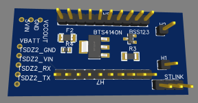
draft_pcb_norouting.png
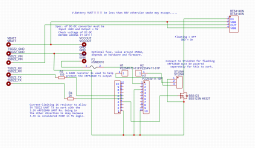
draft_pcb_schematic.png

I've done the easy bit i think - using the schematic on github as the starting point and EasyEDA as it seemed to have a much shallower learning curve than KiCAD - now need to work out how to route it - the mosfets/resistors and fuse are just dumped in the middle of the pcb for now - i'm sure they will get rearranged to make the routing easier. But wanted to make sure I'm not missing anything obvious or if anyone else has any requirements? I know my naming conventions need work - for now I was just trying to get the labels good enough to make the 3d image clear.

Aside from the fact that it makes my first project a bit more complicated - I've not included a DC converter. I'm planning to put a larger DC converter in my case to power USB sockets so thought it better (and easier) to keep it discrete and separate.
 
beemac said:
But wanted to make sure I'm not missing anything obvious or if anyone else has any requirements?
Interesting work although it may be to early to know what can be missing. For now I think we need to prototype DIY, test, develop, test and then we will understand what may be missing.
 
casainho said:
beemac said:
But wanted to make sure I'm not missing anything obvious or if anyone else has any requirements?
Interesting work although it may be to early to know what can be missing. For now I think we need to prototype DIY, test, develop, test and then we will understand what may be missing.

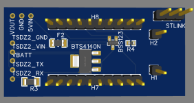
Sure - not about to order any quite yet - was to see how feasible it was (and how long it took me to learn how to do it!). I've had a stab at routing - only one 'via' but can't seem to get it lower than that... Can keep this up to date ready for when we're happy the hardware is at v1.0


draft_pcb_routed.png

Edit: link to the project is here : https://oshwlab.com/beemac/tsdz2-wireless2
 
beemac said:
Can keep this up to date ready for when we're happy the hardware is at v1.0
Very nice!
Should be a great help to new users.
We are switching to the blue dongle so this works out well.
Should be finalizing firmware and circuit design soon.
 
beemac said:
Can keep this up to date ready for when we're happy the hardware is at v1.0

Edit: link to the project is here : https://oshwlab.com/beemac/tsdz2-wireless2
I think would be better if you learn to use KiCAD and also Github, to host your files on it.

See that after we have something more stable and tested, I think we should try to contact the shops before develop a board. They have a lot of contact with users and they may have important feedback for the project as also they may be interested to sell the board and so would give a big boost / success to the project.
 
casainho said:
beemac said:
Can keep this up to date ready for when we're happy the hardware is at v1.0

Edit: link to the project is here : https://oshwlab.com/beemac/tsdz2-wireless2
I think would be better if you learn to use KiCAD and also Github, to host your files on it.

See that after we have something more stable and tested, I think we should try to contact the shops before develop a board. They have a lot of contact with users and they may have important feedback for the project as also they may be interested to sell the board and so would give a big boost / success to the project.

I know it would be nice if it was on github. If i have more time in the coming weeks I might learn kicad but my primary motivation is a cheap board that doesn't mean people have to solder the mosfets particularly the amazingly tiny BS123. I tried soldering a board again today - all new components, prototyping board instead of veroboard this time and again I had the issue where the BTS4140N wouldn't switch off fully - same voltage 4.9v. And I'm pretty sure I fried my last BS123. It is really so small it barely sits between three holes on a 0.1" prototyping board it's just too small for most people I think.

How many people have built a working power part of the board? Is it just me that can't... :? probably... :)

I'm going to leave it a day or so and get on with other things and have another go... might see if I can find some larger mosfets to order in the meantime...
 
rananna said:
beemac said:
Can keep this up to date ready for when we're happy the hardware is at v1.0
Very nice!
Should be a great help to new users.
We are switching to the blue dongle so this works out well.
Should be finalizing firmware and circuit design soon.

Thanks! Yes that's my primary aim... Not saying I don't want to contribute more but getting a design and BOM for a cheap populated board that people can order easily from a service like pcbway is my primary goal.
 
casainho said:
They have a lot of contact with users and they may have important feedback for the project as also they may be interested to sell the board and so would give a big boost / success to the project.

If we were going for a more capable board - then i think the DC-DC converter is one thing. Would also be fantastic there's a way to provide an interface to allow flashing of firmware to all components on the ebike from the app. I need to learn about st-link - is it totally proprietary or can you use an SPI interface for instance...

Box would need to be mounted near the motor (or inside with external antenna) or have a long wire that taps into the speed sensor but being able to spec up a reliable cable harness into the wireless box that you can then use to flash all the firmware and do the wireless stuff too would really lower the barriers to adoption.
 
rananna said:
We are switching to the blue dongle so this works out well.
Should be finalizing firmware and circuit design soon.

Is the switch final and confirmed or the initial Casainho choice will remain supported.
I am asking because I have just received two boards and if they are becoming obsolete and useless for this project, it’s better to not open the boxes and to return them ASAP.
Not even mentioning that the original blue board is twice as cheap as the other.
 
beemac said:
casainho said:
They have a lot of contact with users and they may have important feedback for the project as also they may be interested to sell the board and so would give a big boost / success to the project.

If we were going for a more capable board - then i think the DC-DC converter is one thing. Would also be fantastic there's a way to provide an interface to allow flashing of firmware to all components on the ebike from the app. I need to learn about st-link - is it totally proprietary or can you use an SPI interface for instance...

Box would need to be mounted near the motor (or inside with external antenna) or have a long wire that taps into the speed sensor but being able to spec up a reliable cable harness into the wireless box that you can then use to flash all the firmware and do the wireless stuff too would really lower the barriers to adoption.
We can learn a lot with ESP32-TSDZ2 project: https://github.com/TSDZ2-ESP32/TSDZ2-ESP32-Wiki/wiki
It does program the motor firmware wireless (by the mobile app) while the board is connected only on the display connector.
It is also for mount inside the motor with the advantage that temperature sensor connects directly to this board and so throttle connection is always available.

I wounder if we can implement wireless throttle just like we plan to do with the wireless brake sensor. The wireless board is very small and so it will also be the box. I think will be much easier to install the box outside.
 
plpetrov said:
Is the switch final and confirmed or the initial Casainho choice will remain supported.
I am asking because I have just received two boards and if they are becoming obsolete and useless for this project, it’s better to not open the boxes and to return them ASAP.
Not even mentioning that the original blue board is twice as cheap as the other.
There are many nrf52840 boards that could be compatible with the firmware.
The makerdiary boards are neither obsolete or useless.
However, we wanted to recommend only ONE board to simplify the setup for new users. The reason for the switch is because the Nordic board has a significant battery life advantage over the makerdiary board for operation in the remote control.
I am preparing docs on how to load the new bootloader on the new board that will allow users to load both the remote and the controller firmwares.
This will be available soon.
 
The one area where theres least disruption to both the motor and in regards to opening the motor for warranty purposes and having to physically solder wires, is beneath the plastic cover on the drive side. If you take off the chainring spider and then remove the two screws on the cover, there is quite a big void on the front side.

Now the 6 or 8 pin connector comes out there and it maybe possible to simply loop that connector into the pcb via a compatible connector and then back into the LCD connector via another connector. It would mean least involvement for the computer and electronics illiterate like myself, just plug and play. There is also the benefit that we may only need a pcb mounted aerial as the plastic cover may be not RFI restrictive unlike the cast and aluminium covers on the motor side.
 
@rananna,

I had improved the bootloader startup to be low power, using the same logic as I did for the remote (the remote battery is now 0.15 volts lower after all this time, from 3.05 volts to 2.90 volts).

The code now is more simple (no more resets) and the system blocks in low power while waiting for the 10 seconds timeout or bootloader button release.

My reset button on the board works if I build the code for debug mode, otherwise it does not work...... so, please test the code, hopefully will work for you as I did not changed the buttons interrupt code you did before.
And the lfclk_start() you did was key for me to have the __WFE() working!!

https://github.com/OpenSourceEBike/TSDZ2_wireless-bootloader/tree/improve

// init GPIOS and init the release interrupts if applicable
bootloader_pin_pressed = gpio_init();

// if at least one bootloader button is pressed
if (bootloader_pin_pressed)
{
lfclk_start(); // start the low freq clock (for enter low power next)

// start RTC timer timeout
rtc_config();

// will enter in low power mode and block
// Will unblock and move forward only when timeout happens or one of the bootloader buttons are released
__SEV();
__WFE();
__WFE();
}
 
@ranana,

Seems I have an issue with my microcontroller, [173] GPIO: Writes to LATCH register take several CPU cycles to take effect.
I tested with a VLCD5 remote pin STANDBY__PIN and the code now seems to works:

/* This function is specifically to avoid the follwing issue:
[173] GPIO: Writes to LATCH register take several CPU cycles to take effect */
static __attribute__((optimize("O0"))) bool readPinState(uint32_t pin)
{
nrf_gpio_cfg_input(pin, GPIO_PIN_CNF_PULL_Pullup);

static volatile uint32_t temp;
temp = NRF_P0->IN;
temp = NRF_P0->IN;
temp = NRF_P0->IN;

if (nrf_gpio_pin_read(pin))
return true;
else
return false;
}
 
I just installed the bootloader on my remote and then installed by wireless the firmware.

I could start the bootloader by the long press of UP button, both when I connected the battery (bootloader startup) as also when the firmware was running. I will change the bootloader to start only when user simultaneous long press the four buttons, this way user will not enter on bootloader by mistake, as it is very easy to forget long press the UP button. Also long press of any button as also combinations of buttons long press, should be available for user to control for instance the walk assist. The long press of all buttons will stay reserved for start the bootloader.

On the firmware, the remote could be detected by the Garmin Edge but the detection of click for page change was to slow and was missing most of the times...

My priority for now is to test the bootlader and see if is stable enough to make a public release.

@rananna, what do you think? I hope soon we can finish the bootloader and forget about it, so we can move forward to the firmware development.
 
casainho said:
The code now is more simple (no more resets) and the system blocks in low power while waiting for the 10 seconds timeout or bootloader button

I will test and let you know.
 
casainho said:
I could start the bootloader by the long press of UP button, both when I connected the battery (bootloader startup) as also when the firmware was running. I will change the bootloader to start only when user simultaneous long press the four buttons, this way user will not enter on bootloader by mistake, as it is very easy to forget long press the UP button. Also long press of any button as also combinations of buttons long press, should be available for user to control for instance the walk assist. The long press of all buttons will stay reserved for start the bootloader.

Don't forget we also implemented 0x99 to enter bootloader with Bluetooth from both firmware packages. The simultaneous press of all buttons is kind of tricky to do, maybe just plus+minus together is easier.
I
 
casainho said:
the remote could be detected by the Garmin Edge but the detection of click for page change was too slow and was missing most of the times...
That is very strange. I do not see any noticiable delay on the two garmin edge devices I have or with the garmin simulator. I certainly do not see missed page turns either. Is it a communication issue caused by distance from the board?
 
casainho said:
My priority for now is to test the bootlader and see if is stable enough to make a public release.

@rananna, what do you think? I hope soon we can finish the bootloader and forget about it, so we can move forward to the firmware development.
Sure. I have not completed testing the latest changes you made for power, but there is certainly an issue with the leds not flashing entering dfu mode now. I will continue to look into it.
 
casainho said:
:

/* This function is specifically to avoid the follwing issue:
[173] GPIO: Writes to LATCH register take several CPU cycles to take effect */
static __attribute__((optimize("O0"))) bool readPinState(uint32_t pin)
{
nrf_gpio_cfg_input(pin, GPIO_PIN_CNF_PULL_Pullup);

static volatile uint32_t temp;
temp = NRF_P0->IN;
temp = NRF_P0->IN;
temp = NRF_P0->IN;

if (nrf_gpio_pin_read(pin))
return true;
else
return false;
}
Good catch!
I would never have found that!
 
Back
Top