TSDZ2 EBike wireless standard (like Specialized Turbo Levo) - OpenSource

Hi casainho and others - first thanks for your amazing work on the tsdz2 - I hope I can contribute in some way. I've only recently got an tsdz2 and I've spent many hours getting the OS fw running - it's great.

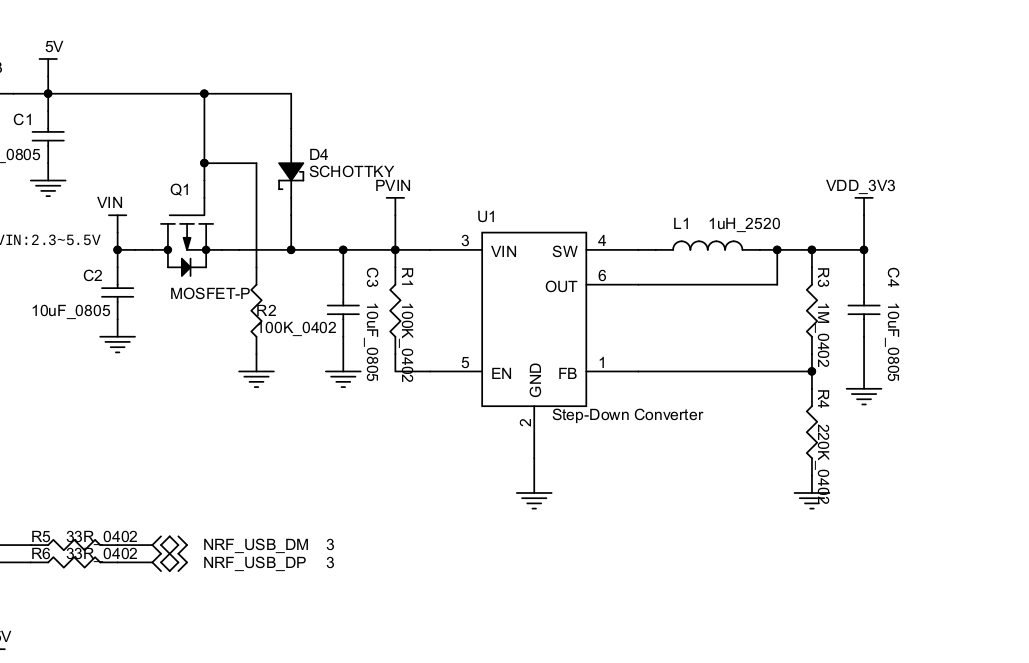
Keen to have a setup without the 860c on my handlebars and also want to help with testing early on I've built my wireless board according to the schematic here:


I'm using the nordic blue dongle - not the mdk. Mosfets are both Infineon brand purchased from mouser - so hoping they are genuine.

Board seems to be working ok except it doesn't switch off fully. I've got a 48v battery fully charged - so when on I get the expected 54ish volts. When off - I still get 4.9v....

The problem seems to be the BTS4140N - I've removed all other components - dc converter etc. and the mosfet just refuses to switch off completely when IN isn't (corrected!) grounded. The smaller BSS123 is working fine - but I've even removed that from the circuit to check. IN floats at the battery voltage if not grounded, so all looks good except OUT never drops below 4.9v when off...

Googling around - static damage would seem to be the obvious cause. I've replaced both mosfets taking pretty good ESD precautions - same results...

Anyone had similar issues?
 
rananna said:
@casainho,

I have been investigating battery options for the remote control when I came across the Adafruit nrf52840 express.
See: https://learn.adafruit.com/adafruit-itsybitsy-nrf52840-express
This board has the significant advantage of including a USB charging port for a 3.7V backpack battery for long life between recharges
see: https://www.adafruit.com/product/2124
Otherwise it is about the same size as the makerdiary board.
This might help simplify packaging, as we could perhaps design a 3d printed enclosure that would expose both the led and USB charging port to the user while allowing for brake connections to the enclosure.
It is also a very inexpensive board like the makerdiary.
Specs attached.
Thoughts?
I think we should have a base board to document but then everyone will probably go with different boards depending on specific advantages.

That board including that battery seems way bigger, starting on the battery itself. I really hope the small CR2032 will work for 1 year, so, why use a bigger battery?

Also, there is probably need to remove / disable everything from the board and make the battery voltage direct to the NRF52 (a CR2032 because it has 3V) so only the NRF52 will use power while on ultra low power mode. I did this test on my current board. You will need to do to that board.
 
casainho said:
Also, there is probably need to remove / disable everything from the board and make the battery voltage direct to the NRF52 (a CR2032 because it has 3V) so only the NRF52 will use power while on ultra low power mode. I did this test on my current board. You will need to do to that board.
What did you disable and how did you do it?
Ie: Did you find you had to de-solder the led or other components?
How did you make a direct power connection to the nrf52? Did you bypass the voltage converter somehow? Maybe use the Vdd 3.3 pin instead of Vin?
Sorry for all the questions, but I want to set up my board with a coin cell to estimate life.
 
rananna said:
casainho said:
Also, there is probably need to remove / disable everything from the board and make the battery voltage direct to the NRF52 (a CR2032 because it has 3V) so only the NRF52 will use power while on ultra low power mode. I did this test on my current board. You will need to do to that board.
What did you disable and how did you do it?
Ie: Did you find you had to de-solder the led or other components?
How did you make a direct power connection to the nrf52? Did you bypass the voltage converter somehow? Maybe use the Vdd 3.3 pin instead of Vin?
Sorry for all the questions, but I want to set up my board with a coin cell to estimate life.
image.png


I had to remove U1, L1, R3 and R4. I had to solder the battery positive wire directly to a small capacitor, near the NRF52.
 
New project page (using Github pages): https://opensourceebike.github.io/

Here is the last version of the Android app, I do not plan to change anything more, only the data on communications to make sure it will work with the firmware on the wireless board.
Download here, just for see it working on your phone: https://github.com/OpenSourceEBike/TSDZ2-Android/releases/tag/v0.1.0

See that there is only one main screen but I added (this feature is not available on the ESP32 project) customization on the fields, a bit like on the 860C display:

[youtube]QU4JChGzGE4[/youtube]

Whats-App-Image-2020-12-07-at-20-43-45.jpg


Whats-App-Image-2020-12-07-at-20-48-58.jpg


Whats-App-Image-2020-12-07-at-20-43-45-1.jpg


Whats-App-Image-2020-12-07-at-20-43-45-2.jpg
 
casainho said:
I had to remove U1, L1, R3 and R4. I had to solder the battery positive wire directly to a small capacitor, near the NRF52.
Thanks for this. The Nordic dongle has sb1 and sb2 solder bridges to disconnect/ connect that seem to accomplish the same thing with a lot less work.
See: https://infocenter.nordicsemi.com/index.jsp?topic=%2Fug_nrf52840_dongle%2FUG%2Fnrf52840_Dongle%2Fhw_power_ext_reg_source.html
 
Hello,

first: thanks to all who made it possible to better use the TSDZ2!

Till now I tried emmebrusa and the ESP32.
Right now I tried the just published Android app. Very nice feature being able to select what to be displayed in the fields!

One little issue/remark: I like to use two apps in split screen (map in second). With the ESP32 app it's not perfect but better viewable:
ESP32.jpg
That's the new app:
Ebike-wireless.jpg

So just a remark, nothing essential...

I just want to use the smartphone on longer trips. For everyday use I'm still looking for a good small display solution showing just the essential. I even consider building a display myself (having also the nice Waveshare 2inch here...).
My primary further wish would be to display the battery percentage delivered by a Xiaoxiang smart bms. Up to now I just tried a Arduino sketch on an ESP32 to connect to the bms.

So for me wireless buttons are not that interesting (re-using the ones from the simple but nice one from the VLCD5 remote I also considered for a potential own display). However following the discussion I just found this small (18x13mm) NRF52840 module. Maybe it might be interesting to use for the buttons?
E73-2G4M08S1C.png
http://www.ebyte.com/en/downpdf.aspx?id=445

Personally I'm wondering if it would make sense to additionally supply UART pins for wired buttons (and a simple display). Maybe using the original Tongsheng protocol so that e.g. a VLCD6 could be used? Bafang protocol would be nice too (so being able to use just one of the many available displays) - however more complicated as I already experienced.
Okay, your aim at this project is wireless...
 
beemac said:
Board seems to be working ok except it doesn't switch off fully. I've got a 48v battery fully charged - so when on I get the expected 54ish volts. When off - I still get 4.9v....

The problem seems to be the BTS4140N - I've removed all other components - dc converter etc. and the mosfet just refuses to switch off completely when IN isn't (corrected!) grounded. The smaller BSS123 is working fine - but I've even removed that from the circuit to check. IN floats at the battery voltage if not grounded, so all looks good except OUT never drops below 4.9v when off...

Googling around - static damage would seem to be the obvious cause. I've replaced both mosfets taking pretty good ESD precautions - same results...

Anyone had similar issues?
Well, I just built one board yet but I hope soon to build another to install on my ebike and then I will test again all this and will better document. I will gives news on this thread.


Beli said:
Very nice feature being able to select what to be displayed in the fields!
Yes, it is the same idea of how Garmin watches and GPS units work, you can choose what each field shows as also custom layouts, like in you case would be better to show less fields (may one less row of fields) .

Beli said:
One little issue/remark: I like to use two apps in split screen (map in second). With the ESP32 app it's not perfect but better viewable:

So just a remark, nothing essential...
I still have things to display on top, like brake and light symbols and so I will try to implement like the bottom rows that seems works better.

Beli said:
I just want to use the smartphone on longer trips. For everyday use I'm still looking for a good small display solution showing just the essential. I even consider building a display myself (having also the nice Waveshare 2inch here...).
My primary further wish would be to display the battery percentage delivered by a Xiaoxiang smart bms. Up to now I just tried a Arduino sketch on an ESP32 to connect to the bms.
I also like the idea of build a small and cheap display, look at previous messages where I shared my ideas:
- https://endless-sphere.com/forums/viewtopic.php?t=106346#p1558436
- https://endless-sphere.com/forums/viewtopic.php?t=106346#p1558708
If you do it, please use easy available DIY hardware and easy programming language, so more users can replicate and development will be easier and faster.

You mean there are firmware for connecting and reading from Xiaoxiang smart bms?? because I have on all my ebikes that BMS and I wish to integrate on the wireless board the communication with that popular BMS.

Beli said:
Personally I'm wondering if it would make sense to additionally supply UART pins for wired buttons (and a simple display). Maybe using the original Tongsheng protocol so that e.g. a VLCD6 could be used? Bafang protocol would be nice too (so being able to use just one of the many available displays) - however more complicated as I already experienced.
Okay, your aim at this project is wireless...
That module is very small for DIY and needs external power supply, the current board stills the best option for DIY.

Adding support for regular displays is not a priority and would not bring differentiation / make this project special. But maybe later, when the best part, the wireless, is already implemented and stable.
 
rananna said:
casainho said:
I had to remove U1, L1, R3 and R4. I had to solder the battery positive wire directly to a small capacitor, near the NRF52.
Thanks for this. The Nordic dongle has sb1 and sb2 solder bridges to disconnect/ connect that seem to accomplish the same thing with a lot less work.
See: https://infocenter.nordicsemi.com/index.jsp?topic=%2Fug_nrf52840_dongle%2FUG%2Fnrf52840_Dongle%2Fhw_power_ext_reg_source.html
That is great!! this is a big plus!! I think this is important enough to discard the other board in favor of this one.
And about the bootloader of this board, do you know if we can flash our own by USB or Bluetooth?
 
For what it's worth, the Specialized Turbo Levo isn't going to have a crank break off out of the blue. So in that respect there's not a good comparison.
 
casainho said:
[
That is great!! this is a big plus!! I think this is important enough to discard the other board in favor of this one.
And about the bootloader of this board, do you know if we can flash our own by USB or Bluetooth?
Yes, that was the reason I bought the board.
I was hoping the bootloader could be changed by usb, but the open bootloader used by Nordic on this board is also signed. You have to use openocd to flash a new bootloader.

I have not tested the Vdd external source with a coin cell yet, but it certainly looks possible
 
rananna said:
I have not tested the Vdd external source with a coin cell yet, but it certainly looks possible
Seems that is the idea of SB1 and SB2. I am pretty sure it will work, at least seems the same I am doing with the other board:

image.png
 
casainho said:
That is great!! this is a big plus!! I think this is important enough to discard the other board in favor of this one.
So, if it helps with battery consumption, should we make the switch to this board for the remote?
 
rananna said:
casainho said:
That is great!! this is a big plus!! I think this is important enough to discard the other board in favor of this one.
So, if it helps with battery consumption, should we make the switch to this board for the remote?
The only thing different is that user do not need to unsolder U1, L1, R3 and R4 and solder the battery positive wire directly to a small capacitor, near the NRF52.
Yes, we should recommend this board for the remote and then, I think probably we should stick with the same board for the whole project.

I am trying to run the firmware but is always giving app_error 34314 here:


Seems you had issues with this... can you revise your changes about FDS for EEPROM? maybe see if configurations on sdk_config.h is ok?
 
casainho said:
.
Yes, we should recommend this board for the remote and then, I think probably we should stick with the same board for the whole project.
Please note also that another advantage of this board is that there is a seperate reset switch to enter the bootloader.
 
casainho said:
I am trying to run the firmware but is always giving app_error 34314 here:


Seems you had issues with this... can you revise your changes about FDS for EEPROM? maybe see if configurations on sdk_config.h is ok?
Yes, I did make changes to this file. Perhaps the sdk_config.sys file did not get properly updated in your repo.
Anyway, I will look at it later today and get back to you.
 
rananna said:
casainho said:
.
Yes, we should recommend this board for the remote and then, I think probably we should stick with the same board for the whole project.
Please note also that another advantage of this board is that there is a seperate reset switch to enter the bootloader.
Yes, that would be nice because I am having that issue to enter in bootloader using the reset pin as IO.

Also should be easy to break by hand the USB connector while on the other board I have to use a saw.
 
casainho said:
I am trying to run the firmware but is always giving app_error 34314 here:
I did confirm that your repo is up to date.
Firmware works fine at my end
error 34314 is defined here:
enum
{
FDS_ERR_OPERATION_TIMEOUT = NRF_ERROR_FDS_ERR_BASE, //!< Error. The operation timed out.
FDS_ERR_NOT_INITIALIZED, //!< Error. The module has not been initialized.
FDS_ERR_UNALIGNED_ADDR, //!< Error. The input data is not aligned to a word boundary.
FDS_ERR_INVALID_ARG, //!< Error. The parameter contains invalid data.
FDS_ERR_NULL_ARG, //!< Error. The parameter is NULL.
FDS_ERR_NO_OPEN_RECORDS, //!< Error. The record is not open, so it cannot be closed.
FDS_ERR_NO_SPACE_IN_FLASH, //!< Error. There is no space in flash memory.
FDS_ERR_NO_SPACE_IN_QUEUES, //!< Error. There is no space in the internal queues.
FDS_ERR_RECORD_TOO_LARGE, //!< Error. The record exceeds the maximum allowed size.
FDS_ERR_NOT_FOUND, //!< Error. The record was not found.
FDS_ERR_NO_PAGES, //!< Error. No flash pages are available.
FDS_ERR_USER_LIMIT_REACHED, //!< Error. The maximum number of users has been reached.
FDS_ERR_CRC_CHECK_FAILED, //!< Error. The CRC check failed.
FDS_ERR_BUSY, //!< Error. The underlying flash subsystem was busy.
FDS_ERR_INTERNAL, //!< Error. An internal error occurred.
};

and is ERR_NO_PAGES

I did increase the defines in sdk_config.sys to allow for 20 FDS data pages, maybe this has something to do with it?
see:
FDS_VIRTUAL_PAGES_RESERVED 20
and
FDS_VIRTUAL_PAGES 20

looking on the nordic website I see disccussion related to not fully clearing flash memory:, maybe check this?
see: https://devzone.nordicsemi.com/f/nordic-q-a/28076/sdk-13-0-fds_init-causes-errors-unless-doing-a-full-flash-erase
 
casainho said:
Yes, we should recommend this board for the remote and then, I think probably we should stick with the same board for the whole project.

OK, but it might be less confusing for end users if we fully switched over to the Nordic board.
That way, the user has to only purchase one board , and the GPIOs would be consistent for the motor controller and the remote.
It would only require an updated schematic in the repo.
 
rananna said:
OK, but it might be less confusing for end users if we fully switched over to the Nordic board.
That way, the user has to only purchase one board , and the GPIOs would be consistent for the motor controller and the remote.
It would only require an updated schematic in the repo.
I don't have that board and I do not plan to buy it as I have a few in stock of the others. I will test with my boards and I hope you can take pictures with your board to be used on the documentation.
Slowly I will build the system and install on my ebike, then I will document.
 
casainho said:
I don't have that board and I do not plan to buy it as I have a few in stock of the others. I will test with my boards and I hope you can take pictures with your board to be used on the documentation.
Yes, I will certainly help with the documentation.
Just to be make sure we are not miscommunicating, you are recommending we switch to the Nordic board for both the remote and the controller, correct? I would not want to see a different board in the controller as discussed ion the previous post.

For the remote, I would propose we use the following GPIOs for the button, 13, 15, 17,and 20 which are all on the same side of the board, instead of 5,6,7,8 used on the MDK52840. Does that work for you?
Vdd and Gnd can be used for the 2032 coin battery.
nRF52840_dongle_press_reset.svg


I will modify the firmware for the new board and change the docs to reflect the change.
 
casainho said:
The idea is to make a quick and dirty board, less components possible and soldering required, so less barriers for new users. This board will be DIY so the success of the project will depend on the easy to source and build!!

I know i'm new here and apologies if this isn't a helpful contribution - but I've read the entire thread and can't see why the circuit needs two mosfets to switch the battery voltage with logic levels - and why the recommended ones are small surface mount parts? I'm waiting on some more mosfets to try building again - to try and get around the issue I have above with off not being off but 4.9V... i'm assuming it's my lack of skill soldering such small parts that are either causing static or thermal damage...

Could we use a single mosfet - in an easier to solder package? The BSS123 in particular is absolutely minute - and even with 35+ years of hobby soldering I found that a problem. It's probably more of an age/eyesight thing :)

I'm no expert and I've probably missed something obvious but a FQP30N06L looks like it would do the job and be much easier to solder. I admit it's a bit more expensive than the two surface mount parts - but it's still less than $1 in single quantities.

https://www.mouser.co.uk/datasheet/2/308/FQP30N06L-D-1809681.pdf

or maybe a 2N7002- is slightly less overspecced - and cheaper. I'm happy to pick up some and do some testing - but not sure if this is all too late to the party!

https://www.mouser.co.uk/datasheet/2/308/NDS7002A_D-1522662.pdf

For a simpler DC converter solution i've chosen a TSR 1-4850WI is also a bit more compact and robust than the variable boards i've seen in postings - and looks to be about the same price.

https://www.mouser.co.uk/datasheet/2/687/tsr1wi-datasheet-1628191.pdf
 
beemac said:
Could we use a single mosfet - in an easier to solder package? The BSS123 in particular is absolutely minute - and even with 35+ years of hobby soldering I found that a problem. It's probably more of an age/eyesight thing :)

I'm no expert and I've probably missed something obvious but a FQP30N06L looks like it would do the job and be much easier to solder. I admit it's a bit more expensive than the two surface mount parts - but it's still less than $1 in single quantities.
The idea of the project is to be easy DIY as possible, so everyone like you (ideally without very basic soldering skills, like already soldering some Arduino wires) can build and use it.
That parts were suggested by other developers after carefully evaluating a possible circuit (the messages at the begin). Then I bought them and tested. All this took a long time. The idea is not being always changing the parts as it takes a long time again to test and document it. But if you think you can improve, please go ahead, test and then share the results.

rananna said:
Just to be make sure we are not miscommunicating, you are recommending we switch to the Nordic board for both the remote and the controller, correct? I would not want to see a different board in the controller as discussed ion the previous post.
Yes, as you, I think is best to use the same board for all the projects. The Nordic board is the best due to being much simple to adapt to run directly from a CR2032 battery.

rananna said:
For the remote, I would propose we use the following GPIOs for the button, 13, 15, 17,and 20 which are all on the same side of the board, instead of 5,6,7,8 used on the MDK52840. Does that work for you?
Vdd and Gnd can be used for the 2032 coin battery.
I remember the other developer to say that there are pins that are bad to connect the buttons pins, because they have some other functions and will use more battery power. I would use the same pins as they were selected carefully by him. Otherwise, I would choose pins near one of others to be easy to solder and not make any mistake.
 
rananna said:
looking on the nordic website I see disccussion related to not fully clearing flash memory:, maybe check this?
see: https://devzone.nordicsemi.com/f/nordic-q-a/28076/sdk-13-0-fds_init-causes-errors-unless-doing-a-full-flash-erase
I just understand that yes, the flash memory must be fully erased. I did lowered the FDS pages to only 2, as a page has 2 kbytes of memory, which is a lot!!

Openocd need to be updated to latest development version to support the nrf5 mass_erase command.

I tried to clean up the main.c file and remove all about bluetooth to other separated file and although the code did build, the final result was not working - I reverted that commit.

I will now focus on the bootloader to see if I can think it needs / can be improved. Then I want to test the remote, change the assist level and see it being changed on the mobile app.
 
casainho said:
beemac said:
Could we use a single mosfet - in an easier to solder package? The BSS123 in particular is absolutely minute - and even with 35+ years of hobby soldering I found that a problem. It's probably more of an age/eyesight thing :)

I'm no expert and I've probably missed something obvious but a FQP30N06L looks like it would do the job and be much easier to solder. I admit it's a bit more expensive than the two surface mount parts - but it's still less than $1 in single quantities.
The idea of the project is to be easy DIY as possible, so everyone like you (ideally without very basic soldering skills, like already soldering some Arduino wires) can build and use it.
That parts were suggested by other developers after carefully evaluating a possible circuit (the messages at the begin). Then I bought them and tested. All this took a long time. The idea is not being always changing the parts as it takes a long time again to test and document it. But if you think you can improve, please go ahead, test and then share the results.

Understood - and I thought it might be the case - is a bit late to start suggesting changes. I'll do a bit more looking about - if I can find compatible through-hole parts to replace both mosfets I'll get some to test.

Another stretch project - which I'm not sure I'll get the time to do - is to learn enough kicad to get a pcbway definition created for a simple board with the the required terminals, dc-converter, mosfets and pins to piggy-back the nrf52840 would be useful... that's another way to solve the almost-invisible mosfet soldering problem :)
 
Back
Top