TSDZ2 mid drive with 860C, 850C or SW102 displays only -- Flexible OpenSource firmware (Casainho code only)

Waynemarlow said:
One of the biggest disappointments of the standard motor is not being able to handle 14S batteries ( the difference between 13S and 14S is night and day on my Bafung which just seems to put the motor into a real sweet spot of power to efficency ) , I would accept a lower current max in lieu quite happily as at 18amps that's over 900W which is way more than you really need for a mid mounted motor on single track trails.
We know there are 2 type of motors: 36V 4000 RPMs and 48V 4000 RPMs (this later works at 52V also, is the same motor). As for the controller, is just the same for all different configurations: supports from battery 20V up to 60V.
 
casainho said:
Waynemarlow said:
One of the biggest disappointments of the standard motor is not being able to handle 14S batteries ( the difference between 13S and 14S is night and day on my Bafung which just seems to put the motor into a real sweet spot of power to efficency ) , I would accept a lower current max in lieu quite happily as at 18amps that's over 900W which is way more than you really need for a mid mounted motor on single track trails.
We know there are 2 type of motors: 36V 4000 RPMs and 48V 4000 RPMs (this later works at 52V also, is the same motor). As for the controller, is just the same for all different configurations: supports from battery 20V up to 60V.

Yes, you can run 52v/14s on EITHER motor actually, the '36v type' motor will just spin a little faster with less torque than the '48v type' motor - but they both are compatible.

I call running 48-52v (54.6-58.8v) on the 36v(42v) motor 'OVERDRIVE'
 
New findings:

1. the original firmware runs with throttle if you connect it

2. Original firmware: PWM scheme seems to be the same as on Kunteng: PWM center aligned and SVM. The motor runs much silent with original firmware than with the block commutation I implemented.

3. Although uses the STM8S105C4 (should have 16kbytes flash memory) and the original firmware seems to use about 15kbytes of flash memory, I was able to flash a 18Kbytes flash memory (our OpenSource firmware for Kunteng controllers) and read after and it is the same -- this means the STM8S105C4 has at least the same flash memory size of STM8S105C6!! This is something that is not new on ST microcontrollers.
 
what are you saying about the memory? that its there? they advertise it as a 16kB controller but really its a 32kB? could be there are bad memory cells in the upper 16kB of the 32kB and they 'Bin' it as a 16kb unit. might be interesting to do a memory write/read test and see where the limit is.
 
nieles said:
what are you saying about the memory? that its there? they advertise it as a 16kB controller but really its a 32kB? could be there are bad memory cells in the upper 16kB of the 32kB and they 'Bin' it as a 16kb unit. might be interesting to do a memory write/read test and see where the limit is.
Good idea to do that test, I would like to do it but I don't have time. Please go ahead :)

stm32f103c8t6 has 128kb flash instead of 64kb...?: http://www.stm32duino.com/viewtopic.php?t=110
 
casainho said:
nieles said:
what are you saying about the memory? that its there? they advertise it as a 16kB controller but really its a 32kB? could be there are bad memory cells in the upper 16kB of the 32kB and they 'Bin' it as a 16kb unit. might be interesting to do a memory write/read test and see where the limit is.
Good idea to do that test, I would like to do it but I don't have time. Please go ahead :)

stm32f103c8t6 has 128kb flash instead of 64kb...?: http://www.stm32duino.com/viewtopic.php?t=110

i will see what i can come up with, and test the code on my kunteng controller, then you can verify if it works on the TSDZ2 controller too.

did you select a different device for compiling (a 32kB device) also, for programming what did you select?
 
On compile for SDCC you just say that is an STM8, so the code is equal over all them.

When flashing the code, we say to stm8flash which device family and I had to say the same as for Kunteng. Wrote and after read a file and verified the bytes, specially the ones after 16k.
 
I am a little confused re battery voltage on the standard units, my 48V unit will not run on anything over 56.6v where as a 14s battery fully charged is 58.6v, are you saying that its the controller which is limiting the upper voltage and that we should be able to reprogramme it to suit ?
 
Waynemarlow said:
I am a little confused re battery voltage on the standard units, my 48V unit will not run on anything over 56.6v where as a 14s battery fully charged is 58.6v, are you saying that its the controller which is limiting the upper voltage and that we should be able to reprogramme it to suit ?
Yes. The hardware supports that range of voltages I wrote before but original firmware is limiting.
 
I thought the hardest part of this project would be putting torque sensor working but that was straight forward because I coild clearly see how the original firmware does.

Now the next part is math!! I am pretty sure there is an math/simple algorithm that has as inputs current and motor speed and outputs the motor phase current angle adjustment value we should apply to implement 'FOC'. I have app notes that shows that vectors and I need to understand the math operations... Anyone can help here??
 
casainho said:
I have app notes that shows that vectors and I need to understand the math operations...

Can you post the link to that app notes?

regards
stancecoke
 
stancecoke said:
casainho said:
I have app notes that shows that vectors and I need to understand the math operations...
Can you post the link to that app notes?

Here: https://opensourceebikefirmware.bitbucket.io/development/EmbeddedFiles/106-SCquals.pdf

Wee need to put I in phase with E. E is in phase is in phase with all sensors signals.
We can measure I module, E module (E = motor KV * motor speed ERPS).
V is our duty_cycle * battery voltage.
We need to measure motor coils L and R.

If there are cosines or such to calc, we need to use a table instead!!

 
In order to do what is explained in the app note you linked to, you need atleast 2 current sensors (third can be calculated) and also these calculations are computation intensive (even with sine/cosine lookup) you should discuss with member Lebowski, He made code for a dspic30 with FOC. So he should have a good idea what would be feasible with the processor we have.
 
nieles said:
In order to do what is explained in the app note you linked to, you need atleast 2 current sensors (third can be calculated) and also these calculations are computation intensive (even with sine/cosine lookup) you should discuss with member Lebowski, He made code for a dspic30 with FOC. So he should have a good idea what would be feasible with the processor we have.
No point to discuss with someone that don't want to share knowledge - Lebowski firmware is not OpenSource.

I think this system does "the thing" with a different approach than traditional FOC. Even that app note, the author went with a different and simple approach than "traditional FOC". For instance, Kunteng controller only has 1 current sensor but still works very well.

After looking better, I think we need to calc the angle of that triangle with side: IwL; IR; V-E. I think is cos teta = IwL / (V-e).
 
I think you know the documentation of Shane Colton? He describes the determination of the best advance angle from the motor characteristics in detail on pages 48ff.

https://github.com/EGG-electric-unicycle/documentation/blob/master/Shane_Colton/3phduo.pdf

regards
stancecoke
 
stancecoke said:
I think you know the documentation of Shane Colton? He describes the determination of the best advance angle from the motor characteristics in detail on pages 48ff.

https://github.com/EGG-electric-unicycle/documentation/blob/master/Shane_Colton/3phduo.pdf
Nice finding!!! I really love Shane Colton documentation!!

I think I will take a brake of this project for a while to advance on Kunteng firmware. But I may be looking at math while then.
 
stancecoke said:
I think you know the documentation of Shane Colton? He describes the determination of the best advance angle from the motor characteristics in detail on pages 48ff.

https://github.com/EGG-electric-unicycle/documentation/blob/master/Shane_Colton/3phduo.pdf


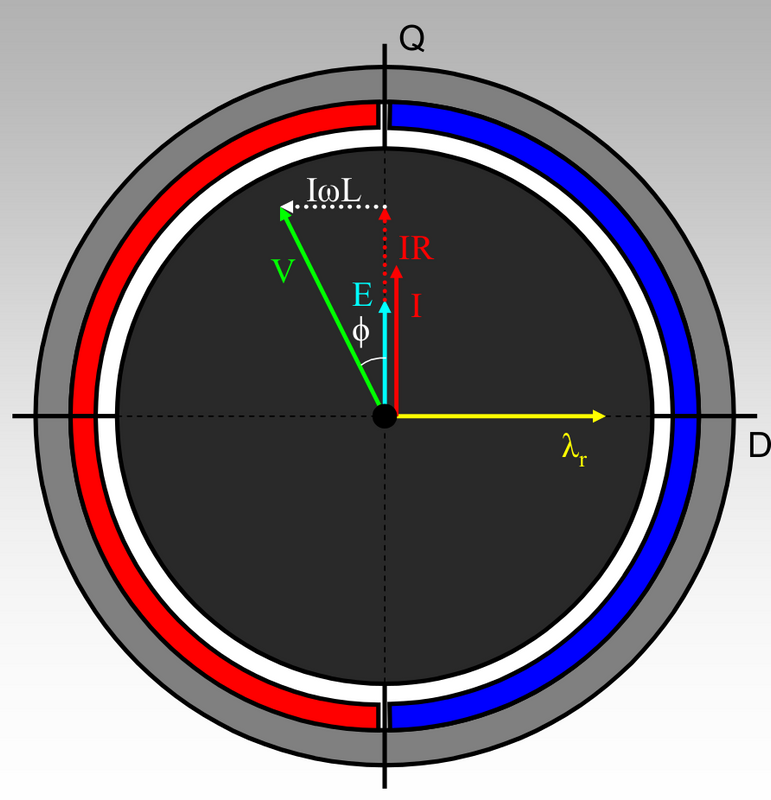
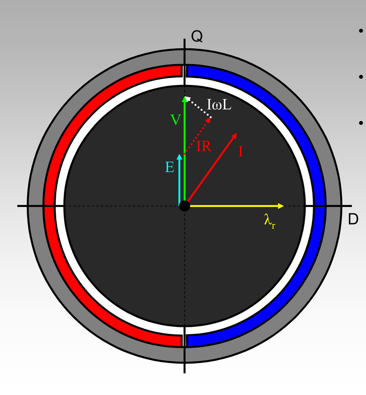
I think will work as a triangle, with sides: V, IwL and (E + IR). I would go with sides V and IwL and that way, Sin teta = IwL / V.
I = (ADC_current*ADC_step)/duty_cycle
w = 6.2831853 * motor_ERPS
L = measure value specific to motor
V = duty_cycle * battery_voltage

Sin-1 ((ADC_current*ADC_step)/duty_cycle * 6.2831853 * motor_ERPS * L) / (duty_cycle * battery_voltage) = teta
where Sin-1 will be stored in a table.

I did put on the STM8 running at 16MHz, with nothing more running on background, it took 775us to do a similar long operation using floats:
Code:
f_8 = (f_1 * f_2 * f_3 * f_4 * f_5) / (f_6 * f_7);
f_8 = f_1 * f_8;

So, if STM8 is busy 66% of time, it may take about 2.5ms to do it. This means that in worst case scenario, at 4000 RPMS, 1 ERPs = 1.875ms, so we could adjust the angle at least every 2 ERPs. This is not far from Kunteng KT controllers, were we do the FOC only every 1 ERPs.
Even some of that operations may be done with integers 32 bits and that will boost 10x, which may mean we can have the same results as Kunteng KT controllers.

Does it make sense??
 
Puh, this makes sense if the advance angle is already set to the right value. Says, current is in phase with the BEMF. You can't use the measured current if you don't know if you are in phase with the BEMF....

I think you have to do this approach:
1. measure the motor specific constants L (inductance) R (coil resistance) and Kv (Motor velocity constant)
2. derive V from Battery voltage and duty cycle
3. derive E from erps and Kv
4. derive angle between V and I according to alpha= arctan(omega*L/R) (see page 49)
5. solve the (non linear) equation system :shock: (iteratively?!, Shane Colten wrote, that he used a geometric solver for this, see page 51)

Equation System.PNG

regards
stancecoke
 
stancecoke said:
Puh, this makes sense if the advance angle is already set to the right value. Says, current is in phase with the BEMF. You can't use the measured current if you don't if you are in phase with the BEMF....
What about the sum of (E + IR)^2 + IwL^2 = sqrt(V) ?? seems to me that when I has angle != 0 with E, that equation in not valid... maybe iterative adjust angle up to get that equation.

Because that V and I has D components when angle != 0, but when D components == 0, we are where we need, just Q components.

????
 
you can try it of course, but I don't know if the iteration will converge with increasing/decreasing the angel incrementally.

but with V² not sqrt (V) :wink:

regards
stancecoke
 
Just registered here after googling around for this motor. Awesome work everyone here is doing!

I'm wondering if you run the engine in the bike with original firmware and modified firmware if the sound/noise level is still the same? It's the thing that's been bothering me. If it's the same, then there is an opportunity to reduce it. If I see it right then this motor is brushless DC as well. With more complex algorithms, these motors can run more smooth and quiet.

If I find time between my other projects and work I'm happy to assist. I'm very familiar with Atmel and ARM(STM) coding and hardware development.
 
Is using the inductance and resistance essential? If so, we need to include a config setting for 36V or 48V motor parameters.
 
jur said:
Is using the inductance and resistance essential? If so, we need to include a config setting for 36V or 48V motor parameters.
I think is a must for the algorithm to use Land R from motor and so yes, there are that 2 different motor versions: 48V and 36V, that both have nominal 4000 RPM.
 
fantasy2 said:
Just registered here after googling around for this motor. Awesome work everyone here is doing!

I'm wondering if you run the engine in the bike with original firmware and modified firmware if the sound/noise level is still the same? It's the thing that's been bothering me. If it's the same, then there is an opportunity to reduce it. If I see it right then this motor is brushless DC as well. With more complex algorithms, these motors can run more smooth and quiet.

If I find time between my other projects and work I'm happy to assist. I'm very familiar with Atmel and ARM(STM) coding and hardware development.
The original firmware runs the motor very silently compared to the 6 steps/square wave/block commutation I implemented. I saw the PWM signals and are SVM just like used on FOC but I think they are simple doing "FOC" using motor parameters!!

The development is blocked because I don't know how to implement "FOC" using the motor parameters... Let's see if jur can help ;)

Please find free time -- if you believe in electric bicycles, improving the environment, improving people's wealth life, on this project your work will have a widder impact simple because TSDZ2 is very popular!! A lot of activity on this forum thanks to it!!

STM8 is very near STM32, the same datasheet types, almost same development tools, the same peripherals, etc. Will be easy for you.
 
casainho said:
The original firmware runs the motor very silently compared to the 6 steps/square wave/block commutation I implemented. I saw the PWM signals and are SVM just like used on FOC but I think they are simple doing "FOC" using motor parameters!!
The development is blocked because I don't know how to implement "FOC" using the motor parameters... Let's see if jur can help ;)
casainho, I have no specific knowledge of FOC, but I have Electrical Engineering background with lots of math etc, so perhaps I can help with that. I need to have a bit more background though. I perused through the document that was posted above (the lengthy one with all the details on FOC) but I need to read it a lot more carefully if I want to help.
What do you mean by " I don't know how to implement "FOC" using the motor parameters"? Can you quickly summarize where you are and what you think is missing?
Jean
(and kudos for all you're doing, it's awesome)
 
Back
Top