• Howdy! we're looking for donations to finish custom knowledgebase software for this forum. Please see our Funding drive thread

TSDZ2 mid drive with 860C, 850C or SW102 displays only -- Flexible OpenSource firmware (Casainho code only)

vshitikov said:
cityboy19 said:
jtsavola said:
vshitikov said:
What are your lights? Is it the official 6v kit. Did it work for you with the previous versions?

Frontlight is Herrmans MR8E (3,3W, 0,75A max) and backlights are three pcs 5mm red leds with resistor. Lights worked without problems when I had TSDZ2 standard software

I have the same. The current of my lamp is 280-290mA

I think it's a version 1.0.0 bug. Someone on github proposed a fix but I'm not sure it fixes it for everyone.

Yesterday I checked ver. 0.9beta2. The same problem.
 
cityboy19 said:
vshitikov said:
cityboy19 said:
jtsavola said:
Frontlight is Herrmans MR8E (3,3W, 0,75A max) and backlights are three pcs 5mm red leds with resistor. Lights worked without problems when I had TSDZ2 standard software

I have the same. The current of my lamp is 280-290mA

I think it's a version 1.0.0 bug. Someone on github proposed a fix but I'm not sure it fixes it for everyone.

Yesterday I checked ver. 0.9beta2. The same problem.

0.8.0 works for me
 
vshitikov said:
cityboy19 said:
vshitikov said:
cityboy19 said:
I have the same. The current of my lamp is 280-290mA

I think it's a version 1.0.0 bug. Someone on github proposed a fix but I'm not sure it fixes it for everyone.

Yesterday I checked ver. 0.9beta2. The same problem.

0.8.0 works for me

And all the versions that worked on the KT-LCD3 up to and including v.0.20.0beta1 work fine at a higher current draw. So yes sounds like a bug in the later 850/860 versions. There is a lot of additional complexity in the later versions of the code. Many of the new arrivals to the project may not be aware but the last release that only worked on the KT-LCD3 is very stable and very polished. A gentleman named Bubba on this forum spent a lot of time on end user improvements and polish when the code split for the newer displays around 0.19 (from mem)

Personally I am very interested in the improved display (more tech info :) ) on the 860c (I bought both a 850 and 860c - still in my project drawer), but I have never made the change because of the number of bugs that would impact me.

I need my bike to be reliable and code stability. 75% of the time I am carrying one or two children on the bike, so lights not working, overruns, and other potential issues are too much risk for me.

Cheers
 
mctubster said:
vshitikov said:
cityboy19 said:
vshitikov said:
I think it's a version 1.0.0 bug. Someone on github proposed a fix but I'm not sure it fixes it for everyone.

Yesterday I checked ver. 0.9beta2. The same problem.

0.8.0 works for me

And all the versions that worked on the KT-LCD3 up to and including v.0.20.0beta1 work fine at a higher current draw. So yes sounds like a bug in the later 850/860 versions. There is a lot of additional complexity in the later versions of the code. Many of the new arrivals to the project may not be aware but the last release that only worked on the KT-LCD3 is very stable and very polished. A gentleman named Bubba on this forum spent a lot of time on end user improvements and polish when the code split for the newer displays around 0.19 (from mem)

Personally I am very interested in the improved display (more tech info :) ) on the 860c (I bought both a 850 and 860c - still in my project drawer), but I have never made the change because of the number of bugs that would impact me.

I need my bike to be reliable and code stability. 75% of the time I am carrying one or two children on the bike, so lights not working, overruns, and other potential issues are too much risk for me.

Cheers

860c really the only advantage is sealed construction so it doesn't get rain in. It still looses to kt lcd for the visibility in direct sunlight. 0.8.0 is pretty stable for general use. I use it on my cargo bike with two kids and firmware never let me down. 1.0.0 is a big change but some people will not get much of it as pedaling over 90 rpm doesn't happen all the time. Casainho has his code open so the bugs will eventually be fixed.
 
hi,

Sorry to hijack this thread, I'm not quite sure of the etiquette here and all questions related to casainho firmware seem to be posted here.

I've just flashed a brand new TSDZ2 and 850C display with the firmware; TSDZ2-v0.57.3.hex and 850C_v1.0.0-trip-bootloader.bin. For a first dip into the opensource TSDZ2 all seemed to go very smoothly!

However, when I power up the system the display shows "Wait TSDZ2" for 30 seconds or so before changing to a message about brakes. I've sniffed the serial line from the motor to the display and I get the following characters transmitted repeatedly, a line every 100ms:

00
1E 30 1E 00 00 00 60 FC

Oddly I can't match this up to any messages that are in the source code, all messages seem to have a start of frame of 0x43?? Have I made some kind of rookie mistake, flashed the wrong version or got something configured incorrectly? I can't imagine it's a hardware issue as the message is so repeatable.

best regards
bomber
 
bomber1973 said:
hi,

Sorry to hijack this thread, I'm not quite sure of the etiquette here and all questions related to casainho firmware seem to be posted here.

I've just flashed a brand new TSDZ2 and 850C display with the firmware; TSDZ2-v0.57.3.hex and 850C_v1.0.0-trip-bootloader.bin. For a first dip into the opensource TSDZ2 all seemed to go very smoothly!

However, when I power up the system the display shows "Wait TSDZ2" for 30 seconds or so before changing to a message about brakes. I've sniffed the serial line from the motor to the display and I get the following characters transmitted repeatedly, a line every 100ms:

00
1E 30 1E 00 00 00 60 FC

Oddly I can't match this up to any messages that are in the source code, all messages seem to have a start of frame of 0x43?? Have I made some kind of rookie mistake, flashed the wrong version or got something configured incorrectly? I can't imagine it's a hardware issue as the message is so repeatable.

best regards
bomber

You have a wrong fw in the motor
https://github.com/OpenSource-EBike-firmware/Color_LCD/releases/tag/860C_850C_SW102_v1.0.0
 
Hey! That's made a difference! Many thanks for the quick help.

I simply went for the latest binaries I could find in the TSDZ2-Smart-EBike and Color-LCD repos. I was surprised by how old the motor one was. Are they normally posted as a released pair then?

bomber
 
Here the news about me start using the wireless buttons. Next I will move to the main wireless TSDZ2 board.

Using a small and cheap 16€ board that implements wireless ANT+, I developed the firmware for ANT+ controls profile. Then I reused, I soldered the wires from the remote VLCD5 display of TSDZ2 to the wireless board. The board is powered with a coin cell CR2032 that I hope will work for at least 1 year (I implemented on the firmware all the ultra low power features possible).

Any mechanical designers capable to design for 3D printing, a mod to reuse the VLCD5 remote board and buttons, adding extra space for this wireless board the the coin cell?

[youtube]O67TSVkCuRM[/youtube]

Repository: https://github.com/OpenSource-EBike-firmware/ebike_wireless_remote

The board is powered with a coin cell CR2032 that I hope will work for at least 1 year - I implemented on the firmware all the ultra low power features possible:

-------------------------------------------------------
• wakeup
☑ any button press (from low power)
☑ any button press (from ultra low power)
-------------------------------------------------------
• enter low power
☑ every time it is not reacting to buttons or rx/tx ANT
☐ every time it is not reading battery voltage
-------------------------------------------------------
• enter ultra low power
☑ if no master / display found (takes about 30 seconds for this detection)
☑ if no button press for 1 hour
-------------------------------------------------------
 
James Broadhurst said:
There is another of these TSDZ2 kits with an 850C display from EJOYQI which is a 6 pin connection unlike EUNORAU which is 5 pin; the extra pin going into the display is the brake which does nothing. I’ve never seen a 6 pin 850C on sale to the EU and EJOYQI do not offer it separately. I haven’t yet tried to flash the motor and display. The motor does work as it is with the display connected
The motor flashes fine with v1.0 and the 850C display behaves as if it accepts the APT burn of v1.0 but it won’t turn on. Bit disappointing as that’s 60 bucks thrown away.

The display serial no is 850C TFTGDV2.3CLB60 JLO2.0 TSA 202003122002

Anyone managed to flash this display from this company’s package?
 
Alphonse said:
Mr.Flibble said:
Alphonse said:
My 860c display reads 1.2 vdc higher than actual battery voltage at a high level SOC. The error decreases to 1 vdc when the battery is at 30% SOC. My assumption is that this is a hardware issue. BTW, my battery is a 52v so yes, I know the displays says "Run" at 59.5V!

Can someone familiar with the workings of an 860c tell me if this is likely a hardware issue or can OSF play into it?

display with wrong voltage - Copy.jpg

actual voltage - Copy.jpg

It's a fault with the controller board, mine did it with the orignal firmware and does it with the osf one too.
Need to be sure what you are talking about here. When you say it is the controller board, do you mean the motor controller or the display board?

I mean the controller board!!!
The controller is located in the motor casing, and is the thing that you flash in addition to the display.
 
Alphonse said:
casainho said:
vshitikov said:
The voltage is measured by the display and soc I guess. and everything else is sent by the controller. There is no protocol published but casainho has his code open so you can easily extract it from there. Expect error of 3 to 5 percent to those values depending on your chip and température . But this does not affect any of the functionality at all. In fact those values are shown to you just for the debugging purpose. What you should only note is the fully charged battery voltage. This voltage is used to reset the soc counter to 100% once you charged your battery. Another thing is put your cutoff voltage to 2.9v per cell. For example 29v for 10S 36V battery. This things doesn't have to be precise and plus minus one volt precision is enough.
Voltage is measures on the motor controller and sent to display. And yes, it is not critical.
@casainho, Thank you for your response. Yes, I did find the actual battery voltage being sent to the display. I measured it at the green connector pins that feed the 860C. Unfortunately my 860C then adds 1.2 vdc to that. So my 860C is showing a voltage that is high by a significant amount.

Could you share what parameters are computed in the Display vs. computed in the Motor Controller? In other words, what data is transmitted to the display on the UART wires? Is there a protocol for the UART published somewhere that you could lead me to?

Thanks again for all your work on this and your help is very much appreciated.

It definitely is a fault, as it stops the motor working with a fully charged battery on the original firmware.
I believe the display is just reporting what the controller tells it.

My BMS and multimeter agree, but the display reports too high a voltage, both with osf and the original.

I also seem to remember reading in the motor thread, about people having to order multiple controllers before they got one that was accurate.
Whether it's hardware or firmware at fault I don't know, but it's definitely the controller.
I guess hardware, as osf reports the wrong voltage too...............
 
I want to start the development for ASI native modbus protocol. I've taken a look into the sources of P850C firmware. In pins configuration, written that EEPROM with I2C interface is connected to PC8 & PC9 ports, but those ports can't be used for I2C core. How can it be?
 
James Broadhurst said:
There is another of these TSDZ2 kits with an 850C display from EJOYQI which is a 6 pin connection unlike EUNORAU which is 5 pin; the extra pin going into the display is the brake which does nothing. I’ve never seen a 6 pin 850C on sale to the EU and EJOYQI do not offer it separately. I haven’t yet tried to flash the motor and display. The motor does work as it is with the display connected
The motor flashes fine with v1.0 and the 850C display behaves as if it accepts the APT burn of v1.0 but it won’t turn on. Bit disappointing as that’s 60 bucks thrown away.
Ouch ... I was trying to flash the bin file not the bootloader file. Apologies. Now works fine.
 
The bike I have built is a family bike ridden by other, less ebike savvy, folks in my household. As I try to tweak and improve the configuration of my OSF, I'd like to be able to review the behavior of the system.

Is there any protocol we could use to add an arduino nano with a datalogging shield to log the data from an 850C?
 
I have a hard time seeing the flashing line under the selected menu items in configuration mode, and was wondering about using some of my design skills to work on the graphics of the OSF UI.

I have some web design experience, but because I have a really hard time debugging code (I can't) I try to work in more wysiwyg editors, but often end up having to futz with the HTML, CSS, and sometimes some Javascript. I did a tiny bit of Arduino programming of a machine controller, but really struggle keeping the syntax straight in all of these, so probably not the right guy for the job.

Nonetheless, I opened the screen.c source code today with with Apple Xcode, and it's not as incomprehensible as I expected. I think I found the section that controls this blinking underline, even if I have no idea what "dirty" means in this C context.

I recall seeing a post, though I have not been able to find it again, by someone who shared some screen shots of a bunch of graphics changes he made to the OSF to make it look more like the factory version, but which didn't feel he could integrate it into this project. Can anyone point me to that exchange, and/or offer any advice on the possibility of my being able to make some simple changes like setting a font color change to the selected field on the config screen?
 
Hello Everyone, Hello Casainho and thank you so much for your enormous work!!! you added so much greatness to these tsdz2 motor out there!!!!
This is my first message here but I built my first bike 7 years ago....now have some bafang for the family and tsdz2 for me!

I recently installed mbrusa porting, due to the simple graphic editor, it seemed to me the right first step to try the opens source firmware!!! Great!!!! I just got back from Dolomite vacations...the bike is perfect!

So now I planned to step to the "dark side of the force" :lol: and put the "real thing" by Master Casainho with a color 850C display I had!
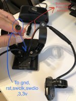
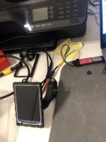
Yesterday I managed to to all the cable mods ( https://github.com/OpenSource-EBike-firmware/TSDZ2_wiki/wiki/Wire-860C-850C-to-TSDZ2 ) and getting prepared to flash it with swd method ( I don't have a boot loader) https://github.com/OpenSource-EBike-firmware/TSDZ2_wiki/wiki/Flash-the-firmware-on-850C-using-SWD .... After that I double checked ALL the soldering and connection schemes.
IMG_2249 copia 2.jpg
I made a small hole to route a 5 pin cable out of the display just right where the other cables come out so I can have a simple access to flash for future release...and used a native tsdz2 connector so it will be pretty much like reprogramming the motor, using the same plugs ( but of course with slightly different pins on the st-link V2 usb device).
IMG_2248 copia.jpg
So.... I'M STUCK! :cry: I cannot make any communication with the STM32 ST-LINK Utility I downloaded ( I did not have it before).... the other software communicate with no problem with my st-link usb device....
Can you help me with a walkthrough ...I feel I'm almost there...but cannot flash this display :lol:
Thank you SO MUCH!
 
electroriderIT said:
Can you help me with a walkthrough ...I feel I'm almost there...but cannot flash this display :lol:
Thank you SO MUCH!
The process does work so something is failing in your case.

- make sure display is powered on, I keep mine powered by connecting to TSDZ2 and keep the ON/OFF button pressed
- check again all your connections
 
casainho said:
electroriderIT said:
Can you help me with a walkthrough ...I feel I'm almost there...but cannot flash this display :lol:
Thank you SO MUCH!
The process does work so something is failing in your case.

- make sure display is powered on, I keep mine powered by connecting to TSDZ2 and keep the ON/OFF button pressed
- check again all your connections

Thank you Master Casainho :mrgreen: .... So I didn't read anywhere the display must be on ( I thought it got some volts from the 3,3v...but now I understand I should connect to motor+battery with the new soldered tsdz2 connector...I did not connect until now because the display has it's own original bafang compatible firmware and did not know if that could cause damages somewhere :twisted: ..... So first I will try to make the procedure with battery connected :bigthumb:
when you say KEEP the on off button pressed you mean KEEP during all flashing process? ( if it will happen to succeed I will make a video for poor guys like me to better understand the flashing details li ke these :eek: )
 
a little update after some tests.
- with display connected to tsdz2 the display powers on, no problem.
- nothing has changed the way the software does not recognize the programmer.

-I checked all 5 wires soldered on the display and they seem to be ok. I also desoldered GND cable from display and checked all other 4 pins with the multimeter to find some problems. the other 4 pins with cables soldered are NOT shortened each other..should be good that way.... When I solder back the GND cable if I test GND with other pins, some are in continuity , but also that should be good due to the connections of the display board (right?)

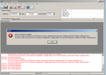
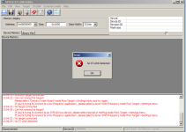
- so everything "connection side" seems fine but I get these errors ( depending on the combination that I use to workaround , in the software jtag, swd, hard reset etc..al the options in stm32 st link software)
Schermata 2020-08-31 alle 13.06.41.png
Schermata 2020-08-31 alle 13.06.17.png
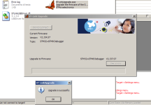
- A curious detail: downloaded the firmware st link update software and it recognize and updates the firmware...BUT then in the stm32 st link software NOTHING!
Schermata 2020-08-31 alle 13.05.41.png
Schermata 2020-08-31 alle 18.48.49.png
 
electroriderIT said:
a little update after some tests.
- with display connected to tsdz2 the display powers on, no problem.
- nothing has changed the way the software does not recognize the programmer.

-I checked all 5 wires soldered on the display and they seem to be ok. I also desoldered GND cable from display and checked all other 4 pins with the multimeter to find some problems. the other 4 pins with cables soldered are NOT shortened each other..should be good that way.... When I solder back the GND cable if I test GND with other pins, some are in continuity , but also that should be good due to the connections of the display board (right?)

- so everything "connection side" seems fine but I get these errors ( depending on the combination that I use to workaround , in the software jtag, swd, hard reset etc..al the options in stm32 st link software)
Schermata 2020-08-31 alle 13.06.41.png
Schermata 2020-08-31 alle 13.06.17.png
- A curious detail: downloaded the firmware st link update software and it recognize and updates the firmware...BUT then in the stm32 st link software NOTHING!
Schermata 2020-08-31 alle 13.05.41.png
Schermata 2020-08-31 alle 18.48.49.png
Is possible your display is not working anymore, it could be damaged for some reason in the process, this kind of things happen.
 
So strange because the display still has its original Bafang compatible firmare that works on it!

Ps: maybe I'll try to get a Bootloader box.... :!: Does anyone know if any user of the forum can build one for me?


casainho said:
electroriderIT said:
a little update after some tests.
- with display connected to tsdz2 the display powers on, no problem.
- nothing has changed the way the software does not recognize the programmer.

-I checked all 5 wires soldered on the display and they seem to be ok. I also desoldered GND cable from display and checked all other 4 pins with the multimeter to find some problems. the other 4 pins with cables soldered are NOT shortened each other..should be good that way.... When I solder back the GND cable if I test GND with other pins, some are in continuity , but also that should be good due to the connections of the display board (right?)

- so everything "connection side" seems fine but I get these errors ( depending on the combination that I use to workaround , in the software jtag, swd, hard reset etc..al the options in stm32 st link software)
Schermata 2020-08-31 alle 13.06.41.png
Schermata 2020-08-31 alle 13.06.17.png
- A curious detail: downloaded the firmware st link update software and it recognize and updates the firmware...BUT then in the stm32 st link software NOTHING!
Schermata 2020-08-31 alle 13.05.41.png
Schermata 2020-08-31 alle 18.48.49.png
Is possible your display is not working anymore, it could be damaged for some reason in the process, this kind of things happen.
 
electroriderIT said:
So strange because the display still has its original Bafang compatible firmare that works on it!

Ps: maybe I'll try to get a Bootloader box.... :!: Does anyone know if any user of the forum can build one for me?


casainho said:
electroriderIT said:
a little update after some tests.
- with display connected to tsdz2 the display powers on, no problem.
- nothing has changed the way the software does not recognize the programmer.

-I checked all 5 wires soldered on the display and they seem to be ok. I also desoldered GND cable from display and checked all other 4 pins with the multimeter to find some problems. the other 4 pins with cables soldered are NOT shortened each other..should be good that way.... When I solder back the GND cable if I test GND with other pins, some are in continuity , but also that should be good due to the connections of the display board (right?)

- so everything "connection side" seems fine but I get these errors ( depending on the combination that I use to workaround , in the software jtag, swd, hard reset etc..al the options in stm32 st link software)
Schermata 2020-08-31 alle 13.06.41.png
Schermata 2020-08-31 alle 13.06.17.png
- A curious detail: downloaded the firmware st link update software and it recognize and updates the firmware...BUT then in the stm32 st link software NOTHING!
Schermata 2020-08-31 alle 13.05.41.png
Schermata 2020-08-31 alle 18.48.49.png
Is possible your display is not working anymore, it could be damaged for some reason in the process, this kind of things happen.

You can buy bootloader box here: https://www.eco-ebike.com/products/...g-and-play-tsdz2-open-source-firmware-updater
 
Hi,

Can anybody help me with the right way to revert to stock firmware?

I have installed the 1.0.0 version together with a 860C display without any issues, based on everything I found here, thank you very much! Did the calibration, all's well. My only slight concern is that the autonomy seems lower, but as this is highly subjective I thought of testing it. So I prepared a standard test, running until the battery was dead, in stages of 5% of SOC% taking notes of the assist level, duration per stage, distance and speed for each stage. Just for info, I ran the motor 10% of SOC in assist 6, 70% assist 8 and 20% assist level 10, with a relatively loaded touring bike. The result was a 4h46' 109km ride, mostly flat (+256m) with a 22.5 km/h average speed.
Now, I would like to repeat exactly the same ride with the stock firmware and my stock VLCD6. I tried, as advised before I started the changes, to flash the motor again with the backup that I made of the stock firmware before installing the OSF 1.0.0. I can flash it, but then there is no reaction to the VLCD6. I tried the VLCD6 on another motor with stock firmware and it works. Is there anything more/different that I should do?

I am amazed by the trove of information that you have so kindly contributed with, so thank you again for your help.
 
electroriderIT said:
So strange because the display still has its original Bafang compatible firmare that works on it!

Ps: maybe I'll try to get a Bootloader box.... :!: Does anyone know if any user of the forum can build one for me?


casainho said:
electroriderIT said:
a little update after some tests.
- with display connected to tsdz2 the display powers on, no problem.
- nothing has changed the way the software does not recognize the programmer.

-I checked all 5 wires soldered on the display and they seem to be ok. I also desoldered GND cable from display and checked all other 4 pins with the multimeter to find some problems. the other 4 pins with cables soldered are NOT shortened each other..should be good that way.... When I solder back the GND cable if I test GND with other pins, some are in continuity , but also that should be good due to the connections of the display board (right?)

- so everything "connection side" seems fine but I get these errors ( depending on the combination that I use to workaround , in the software jtag, swd, hard reset etc..al the options in stm32 st link software)
Schermata 2020-08-31 alle 13.06.41.png
Schermata 2020-08-31 alle 13.06.17.png
- A curious detail: downloaded the firmware st link update software and it recognize and updates the firmware...BUT then in the stm32 st link software NOTHING!
Schermata 2020-08-31 alle 13.05.41.png
Schermata 2020-08-31 alle 18.48.49.png
Is possible your display is not working anymore, it could be damaged for some reason in the process, this kind of things happen.

be sure your 850c is compatible with the firmware. Mine it wasn´t seems like had less memory avaible for the firmware and I couldn´t flash with OSF. I suspect there are many version of the 850c.
 
danj said:
Hi,

Can anybody help me with the right way to revert to stock firmware?

I have installed the 1.0.0 version together with a 860C display without any issues, based on everything I found here, thank you very much! Did the calibration, all's well. My only slight concern is that the autonomy seems lower, but as this is highly subjective I thought of testing it. So I prepared a standard test, running until the battery was dead, in stages of 5% of SOC% taking notes of the assist level, duration per stage, distance and speed for each stage. Just for info, I ran the motor 10% of SOC in assist 6, 70% assist 8 and 20% assist level 10, with a relatively loaded touring bike. The result was a 4h46' 109km ride, mostly flat (+256m) with a 22.5 km/h average speed.
Now, I would like to repeat exactly the same ride with the stock firmware and my stock VLCD6. I tried, as advised before I started the changes, to flash the motor again with the backup that I made of the stock firmware before installing the OSF 1.0.0. I can flash it, but then there is no reaction to the VLCD6. I tried the VLCD6 on another motor with stock firmware and it works. Is there anything more/different that I should do?

I am amazed by the trove of information that you have so kindly contributed with, so thank you again for your help.
Did you reflash back the original option bytes?
 
Back
Top