Eastwood said:
amberwolf said:
They just ground whatever voltage the controller outputs, whenever they are activated by magnets.
Right, but shouldn’t it read close to 5 V on some of the rotation of the wheel?
No, at least, not necessarily. In your case, no. (unless your controller is defective or programmed wrong).
The signal line voltage comes from the controller, not the hall, for motor halls. (throttle halls work differently).
The hall does not output a voltage at all.
The hall only grounds the voltage the controller places on the signal line. It does this when it is "on", meaning whenever a magnet has triggered it (exactly what conditions trigger it depend on the specific hall sensor.
Any voltage you read there comes from somewhere else. If you disconnect the hall signal wires from the controller while still leaving the power wires, you may get a stray voltage on the signal line, that's induced into your meter wires and/or the motor-side hall signal wires, but it is not coming from the halls themselves.
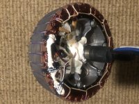
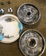
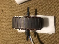
The exception to this is if the motor has a board inside it that the halls connect or mount to, and that board has built-in signal pullup resistors or other electronics, but the voltage still isnt' coming from the halls, it is then coming from this board. This is pretty rare, mostly seen isnide geared hubmotors, or more expensive OEM-bike motor systems, and is not usually seen in motors sold as bare motors or as generic "kits". Even QSMotor doesn't use this system in any of the motors I've seen opened up. I don't see it in your motor, either.
The maximum voltage you can see on the hall signal lines is that which comes from the controller on those signal lines.
The minimum voltage (when a hall is turned on by a magnet) is typically around 0.8v, but can be lower or higher, depending on interference, noise, resistance, etc. Usually it's just called "ground" or "0v" or "low", even when it is not actually at those voltages, for convenience.
The typical voltage on the signal line when not turned on by a magnet will be something around what the controller places on the signal line, depending on interference, noise, resistance, etc. Usually it's just called "5v" or "high", even when it is not actually at that voltages, for convenience.
But the real voltage you will see depends mostly on your controller's actual output.
Some of them output 5v, some 12v, and some less than either by whatever amount their internal electronics (usually a protective voltage divider, etc) reduce that signal pullup voltage to.
Also being the red wire is actually reading 5 V so I would think the 3 hall sensors would be reading close to that.
That is just hte hall power supply. It has nothing to do with the voltage you see on the signals, since it doesn't come from the same place.
The hall signal line can read a MUCH higher voltage than the supply to the halls, or it can read lower, or similar. That is because they are completely separate sources. The supply voltage *can* be used for this, via the pullups in the controller (since the halls don't output anything), but that is not done in all controllers (just most of the typical ebike types).
I don't know how else to explain the operation of these, without getting into schematics and detailed explanations at an electronics-internals level, which is going to take a lot of posting back and forth to ensure each concept gets across.
")
I can do that if you like.
If you won't or can't accept my explanation of how these work, you can look up the spec sheet for the typical motor hall sensor (honeywell SS411 or SS41, etc) you can see how it is internally designed, using an open-collector transistor output (sometimes darlington pair style). If you don't know how that works, there are electronics sites like http://AllAboutElectronics.com that can teach you.