KT motor controllers -- Flexible OpenSource firmware for BMSBattery S/Kunteng KT motor controllers (0.25kW up to 5kW)

I’m still not clear on the wiring of X4 and the white torque sensor wire from the Sempu T4

I wire the white sensor from the Sempu T4 to X4 ?
I wire the White, Red, Black wires from the thumb throttle to the controller throttle connector ?

Sorry for all the questions.

Here’s the English translation from the German forum . :

Here it is described how a torque sensor can be connected. General information on torque sensors can be found here: Torque sensors for pedelecs

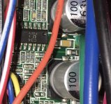
The torque sensor typically provides a pulsed speed signal like a PAS and an analog torque signal like a thumb throttle. The connection is correspondingly simple. If you want to operate a thumb gas parallel to the torque sensor, the torque signal must be connected to connection X4, see Chapter 2 at the bottom. The torque sensors usually require their own power supply, which can be provided from the battery voltage via a DC / DC converter.

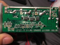
Here is an example of an E-Rider T9 sensor
 
silentguy said:
I wire the white sensor from the Sempu T4 to X4 ?
I wire the White, Red, Black wires from the thumb throttle to the controller throttle connector ?
Yes, but you have to use the Torque_from_X4 branch for this setup.

The T4 sensor works directly with 36V, so you don't need a DC/DC converter in this case.

regards
stancecoke
 
Thanks again stancecoke.

I will try it with the Torque from T4 branch of the firmware you have linked.

I was using a different branch.
 
I flashed the kt36svpr with torque T4 branch of the firmware
It said program memory succeeded.

Update : couldn’t get the torque sensor working.

I’ve wired everything correctly I think but the throttle doesn’t work nor the motor turn at all.

I switched to just trying to get thumb throttle and PAS magnet sensor working first to confirm that the controller works.
I’m using known KT 36 firmware from the Master branch

The throttle turns the motor to about 10mph for a brief time then stops.
The PAS speed/ cadence sensor at the crank does the same thing

I think I need to adjust the hall phase angles now ?
I saw someone just did this , I’ll look at that post but any advice appreciated as well.

Also I am using a KT lcd5. I assume this is same as KT lcd3 for using the OSEC parameter configurator GUI , since there is no choice for lcd5, only lcd 3.

Is there some specifics I’m missing about lcd5 ?

I’ll post a pic of the firmware settings I am using.

Thanks

C5B05107-ED9B-4E42-A7DD-C1E571E54963.jpeg


This is the ini file

12
40
3125
1375
40
80
185
116
150
500
0
237
76


30
45
60
80
100
50
50
50
1500
0.5
0.1
106

1.9
false
64000
40
127


true
false


false
1
43
86
128
false
false
171
213
0.0
12930
69
128
225
 
My own experience is that T4 output voltage is variable across different supply voltage. IT means that at max battery voltage IT will produve higher output values. While at lowest battery voltage it will produce lower output values at the same torque level. That is why i have used DC/DC converter to provide stable 12or 24V where T4 works stable. Best would be test you sensor output voltage at max and minimum battery voltage supply so could see for yourself
 
szkuba said:
My own experience is that T4 output voltage is variable across different supply voltage. IT means that at max battery voltage IT will produve higher output values. While at lowest battery voltage it will produce lower output values at the same torque level. That is why i have used DC/DC converter to provide stable 12or 24V where T4 works stable. Best would be test you sensor output voltage at max and minimum battery voltage supply so could see for yourself


Thanks for that advice. I’m using 36V battery
So it varies from 41 to 31v
I’ll look into the dc-dc later.
For now I’ve just bypassed the T4 Sempu and will try to get PAS and throttle working on the same KT36svpr controller.
 
szkuba said:
That is why i have used DC/DC converter to provide stable 12or 24V where T4 works stable. Best would be test you sensor output voltage at max and minimum battery voltage supply so could see for yourself

Do you have link or recommendation for a good dc-dc step down circuit.
I think I’ll try to find both a 40v and 60v one.
 
silentguy said:
Update : couldn’t get the torque sensor working.

Hm, it would be helpful to connect a USB-TTL converter or a Bluetooth module and flash the firmware in debug mode to see what's going wrong.

If the motor is not running properly, you have to adjust the motor specific angle first.

regards
stancecoke
 
I got it to work with the torque sensor Sempu T4

I had to change gear ratio to 50 when using internal speed sensor.

Its a single fixed gear on the rear , 52tooth chain ring at the front.

For external speed sensor I adjusted the throttle voltages and it seemed to mostly work.

I had some other problems. , I think a short, as the mosfet started smoking. Heat sink got very hot.

It was getting too hot. I did limit the current and voltage but I think the 7A rating on this KT was not enough.

I’ll need to order a 9 mosfet KT now.
 
What is the 51ohm resistor doing.?
There’s a heat resistant heat shrink tube on one of the leads.
See mouse arrow in the pic near the blue wire , it pointing at the resistor

Is it a fuse ?

Reason I ask is mine is burnt out.

What should I replace it with ?
Fuse of some value ?
I can find a 51 ohm resistor but I’m not sure about the other lead side.

It came that way from the seller.
Used controller I think. F8CD3DF5-33D5-4E7F-8861-CBDA13DC8119.jpeg
 
Ok I found that it’s just a resistor with a heat resistant tube.

I ordered a 6 watt resistor as it’s a bit stronger.


5FFC4757-4E10-4D49-86CB-78DB78534303.jpeg
 
I have went through last 20 pages of the thread but did not found the answer what is behind to those perimeters:
1. Dynamic assist level?
2. Speed influences Tq Sensor?
can someone explain would be great to understand :)
3. I was wandering how the cadence is being calculated? Is this the number of impulses in defined perios of time like 0,5 sec or any other way is this calculated
4. Would the KT-LCD4 work with open firmware?
 
F462E362-3D25-436D-8DB9-9680718A490D.jpeg290FD619-AEEE-4C01-8C2C-4B5488CC3D20.jpeg8F6CC188-3E52-44E5-B753-EEE68BD28949.jpeg3D54B5AD-131B-4CBF-85EE-BD91289524C8.jpegThe LSW1031 is from the Sempu T4 torque sensor.

I’d be happy to help test the open source firmware.

More pics.
 

Attachments

  • A9F46E7F-2983-42A5-BDD4-9053BFDA0F67.jpeg
    A9F46E7F-2983-42A5-BDD4-9053BFDA0F67.jpeg
    62.4 KB · Views: 1,848
Some clearer pics of the chips on the pcb
 

Attachments

  • 35F4EF20-C09B-47A3-A925-3407A207F502.jpeg
    35F4EF20-C09B-47A3-A925-3407A207F502.jpeg
    75.8 KB · Views: 1,840
I have the StlinkV2 programmer and I’m willing to overwrite the stock firmware on this LSW1031 as it is not very good. Only 2 settings can be changed. Backlight brightness and tc which I’m not sure what it does.
It’s also speed limited to 25kmh and I would like to remove this for USA

I’ll give it a try to flash the open source fw.
I see the 3 shunts, 3 half bridge drivers , the STM 32,
and on the top side of the pcb is the other chip ?
Not sure if it’s the right one it says C34 ?
I’ll wait to flash as I don’t think this chip is the same
 
silentguy said:
I’ll wait to flash

Thank you for the photos! The open source firmware should work with this controller.
You have to check to which processorpin the torque-signal is connected. With the open source firmware it has to be connected to the throttle input. But this can be changed quite easily in the source code.

Where have you buyed the controller? From Phoebe Liu at Aliexpress?
What kind of display was delivered with the controller? I've implemented several displays already, but the one in the link seems to be new/different.

We should start a new thread for the Lishui firmware.

regards
stancecoke
 
szkuba said:
1. Dynamic assist level?
You have to ask Xnyle for that feature :)

szkuba said:
2. Speed influences Tq Sensor?
If you activate this, the assist factor increases with the speed (for lazy commuting :))

szkuba said:
3. I was wandering how the cadence is being calculated?
The number of timertics (@16kHz) between two PAS interrupts are counted.

szkuba said:
4. Would the KT-LCD4 work with open firmware?
I've not tested it, but I think yes. It should use the same communication protocol as the LCD 3/5 diplays.

regards
stancecoke
 
Back
Top