KT motor controllers -- Flexible OpenSource firmware for BMSBattery S/Kunteng KT motor controllers (0.25kW up to 5kW)

Regarding my last post, after another reflash :wink: i got diagnostics mode communication, but strangely it is showing me settings i didn't set, like having the torquesensor enabled or duty cycle static zero enabled and pwm power off. None of them have been enabled in any of my prior flashes, wich strengthens my theory of an problematic microcontroller...
 
Touffik said:
Hello guys, and thanks for this great thread and work for an open source firmware.
I am trying to build a new ebike with the following setup:
- Bafang TQ sensor SR PA231.32.ST
- Bafang autoshift 2 speed (but TBH I have no clue how to use that with the KT controller)
- Throttle for a lazy mode
- 18 Mosfet KT controller
- dual 15s batteries in parallel (Max 63v)
- KT LCD3
- I have replaced the 2 resistors and 2 LM by a 15v bucket

I'm using the Torque from X4 fork of the GitHub.

I have few questions I would like to check with you guys.
1) The first strange behavior with the LCD was probably linked to the XOR checksum : display was not providing any useful infos.
Yet, I provide here some hints for other users but let me know if I didn't get the point. So I sniffed the Tx line from the LCD and got the following packets: (I just supposed that 0x0E was the terminal byte like other screens but I'm not sure actually) : 0x12,0x05, 0xF4, 0x5C, 0x20,0x5C,0x18,0xEA,0x04,0x14,0x01,0x32,0x0E. I run the tool in the wiki and got the output attached to this post. I just supposed that I have to select the ui8_j value where (ui8_crc^ui8_j) and ui8_rx_buffer[5] matches, therefore 28 but actually I have no clue here. I then added ((ui8_crc ^ 28) == ui8_rx_buffer [5]) in the display.c file and actually LCD then begins displaying stuff. So I guess that's fine.

2) I noticed a second strange behavior with the LCD : every time I plug the battery, display turns on. When I want to turn it off, I can using the switch but then when I want to turn it on again it doesn't work. However I have noticed that the throttle can work when the display is off. Any advise here ?

3) I followed the mapping of this https://www-pedelecforum-de.transla...l=auto&_x_tr_tl=fr&_x_tr_hl=fr&_x_tr_pto=wapp even if my colours where differents I used the pint numbers. Then made this wiring:

BB TQsr >>>>>>> KT controller
Pin 1 : GND >>>>>> GND black wire from the PAS plug
Pin 5 : 5V+ >>>>>> +5V brown wire from the PAS plug (actually it's more 4.5v but anyway)
Pin 3 : Torque >>>> X4 wire from the PCB
Pin 4 : PAS >>>>>>> PAS Yellow wire from the PAS plug

not sure it's really working actually but still need to investigate the option of the OSEC configurator. It seems that the wheel (in the air) tries to keep the same speed even when I stop pedaling, but I don't feel the acceleration of the motor speeding up when I pedal faster. Yet the thumb throttle works. Any advise here too?

here are some measures I took :
With TQsensor plugged in
GND - brown(input): 4,3v
GND - PAS signal: 4,7v
GND - x4 (torque): 0,74v

Without TQsensor plugged in
GND - brown(input): 4,3v
GND - PAS signal: 5v
GND - x4 (torque) : 1.2v

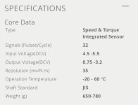
The Bafang states the following :
IMG_77D68CEFF955-1.jpeg

I'm using the following parameters:
uint16_t ui16_X4_min_range = 310
uint16_t ui16_X4_max_range = 900

Torque calibration : 80

When monitoring in Diagnostic mode ui16_sum_torque and uint32_torquesensorClabration I just have 0, 80 even when I action the torque sensor.

Anyone might have some ideas of what I'm not doing right here?
thanks
 
I'm using the following parameters:
uint16_t ui16_X4_min_range = 310
uint16_t ui16_X4_max_range = 900

Torque calibration : 80

When monitoring in Diagnostic mode ui16_sum_torque and uint32_torquesensorClabration I just have 0, 80 even when I action the torque sensor.

Sorry, can't answer all your questions, but a couple of observations here:-

I think your numbers for min/max values here are a little off - I believe these numbers are based on 5v = 1024 adc, so I think they should be:-

(0.75/5) x 1024 = 153.6

and

(3.2/5) x 1024 = 655.36

...in reality I would use 155 and 650 here.

Also, be prepared to play around with the 'Torque Calibration' setting. I don't know how the code uses this parameter, I found the sort of number you're using was ok, but you may need to experiment here.

Would also add that I'm not a coder, so don't take any of my answers as gospel... :?
 
thanks for the quick answer @Geofft

I updated the number but it hasn't solved yet my issue. Some additional information regarding the voltage
When looking at the voltage between the PAS signal and ground I get the following voltages: 2.4v or 5.7v whether it's in front of a magnet or not I guess, and 3.6V when I am pedaling continuously.

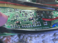
Also, I remember one of your post where you uploaded a simple scheme of the x4 layout. Following this, I was able to remove the pull-up to the 5v on my 18mos board (below the Zener diode). However, I could't really check that something is wired between X4 and the 0v line with a 104 resistor. You may have noticed in my prior post that the voltage of the X4 is 1.2v (without the tqsr wired) while it should be lower around 0v right?

One last stupid question, if I do my tests with the wheel in the air, of course there is no resistance so torque stays low. But does the KT refuses to provide assistance because it can't feel the resistance? PAS signal is not enough for assisting wheel? I tried to maintain the wheel with my hand and create some resistance. The voltage increases but the diag tools still shows 0.
tempImage6eiiOl.gif
 
You may have noticed in my prior post that the voltage of the X4 is 1.2v (without the tqsr wired) while it should be lower around 0v right?

Hmm...the thorny subject of the X4 circuitry arises again. You're correct, X4 (for our purposes) should be at 0v. It sounds like the input is now floating, I'm guessing that you've removed the pullup resistor but still need to replace it with a pulldown. It would seem that there are some KT pcb's out there with X4 pulled up to 5v.

One last stupid question, if I do my tests with the wheel in the air, of course there is no resistance so torque stays low. But does the KT refuses to provide assistance because it can't feel the resistance? PAS signal is not enough for assisting wheel? I tried to maintain the wheel with my hand and create some resistance. The voltage increases but the diag tools still shows 0.

....when things are working correctly, with the wheel in the air it should immediately spin up till it hits whatever speed limit applies and then coast down till it's below the speed limit and the cycle then repeats ad infinitum. I don't think the KT controllers have any mechanism that can detect lack of wheel resistance other than applying the speed limit. Would suggest you get your X4 circuit configured correctly before you look anywhere else...
 
geofft said:
Hmm...the thorny subject of the X4 circuitry arises again. You're correct, X4 (for our purposes) should be at 0v. It sounds like the input is now floating, I'm guessing that you've removed the pullup resistor but still need to replace it with a pulldown. It would seem that there are some KT pcb's out there with X4 pulled up to 5v.

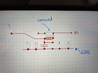
Yeah… I’ve tried to follow the trace and you can find it below. Dashed lines in red is not relevant components and blue dashed line is the component I removed when it was 5v. Comparing to the one you uploaded in the past, I was expecting a space to solder a pull down resistor.
image.jpg
 
Touffik said:
geofft said:
Hmm...the thorny subject of the X4 circuitry arises again. You're correct, X4 (for our purposes) should be at 0v. It sounds like the input is now floating, I'm guessing that you've removed the pullup resistor but still need to replace it with a pulldown. It would seem that there are some KT pcb's out there with X4 pulled up to 5v.

Yeah… I’ve tried to follow the trace and you can find it below. Dashed lines in red is not relevant components and blue dashed line is the component I removed when it was 5v. Comparing to the one you uploaded in the past, I was expecting a space to solder a pull down resistor.

I think simply wiring a 100k (104) resistor directly between ground and the X4 connection would do the job...?
 
geofft said:
Touffik said:
geofft said:
Hmm...the thorny subject of the X4 circuitry arises again. You're correct, X4 (for our purposes) should be at 0v. It sounds like the input is now floating, I'm guessing that you've removed the pullup resistor but still need to replace it with a pulldown. It would seem that there are some KT pcb's out there with X4 pulled up to 5v.

Yeah… I’ve tried to follow the trace and you can find it below. Dashed lines in red is not relevant components and blue dashed line is the component I removed when it was 5v. Comparing to the one you uploaded in the past, I was expecting a space to solder a pull down resistor.

I think simply wiring a 100k (104) resistor directly between ground and the X4 connection would do the job...?

Well I used a 10k one and it drops to 0v so it should be good now.
Yet even if I can read voltage correctly when pedalling, I don’t see any effect on the motor. Now I fixed the x4 voltage, the only remaining option to be investigated is to test different values of torque calibration in the x4’s fork?
 
Well I used a 10k one and it drops to 0v so it should be good now.

.....ideally it would be 100k but 10k may be ok.
Just to be doubly sure, with a voltmeter connected to X4 can you confirm that:-

a) When you connect the torquesensor (pedals free) it pulls X4 up to its minimum voltage, i.e. 0.75v

b) When you apply weight on the pedals the X4 voltage rises above 0.75v. With full weight it should approach somewhere near its max output voltage i.e. 3.2v.
 
andrea_104kg said:
......
I went back to the original design, a self-built mid motor with a hub converted to a mid motor.
The motor is a q100h modified by me to turn the axis....
Do you have the convertion of that motor somewhere described on this forum? Also can you share how did you mechanically connected the TQ sensor and frewheell?
 
geofft said:
Well I used a 10k one and it drops to 0v so it should be good now.

.....ideally it would be 100k but 10k may be ok.
Just to be doubly sure, with a voltmeter connected to X4 can you confirm that:-

a) When you connect the torquesensor (pedals free) it pulls X4 up to its minimum voltage, i.e. 0.75v

b) When you apply weight on the pedals the X4 voltage rises above 0.75v. With full weight it should approach somewhere near its max output voltage i.e. 3.2v.
Yes for a) and for b) I was able to go to 2.3v using hands buts I’m sure it could reach 3.2v if I was in a real situation pedalling with my legs in a hill lol.
 
Yes for a) and for b) I was able to go to 2.3v using hands buts I’m sure it could reach 3.2v if I was in a real situation pedalling with my legs in a hill lol.

...ok, that means that your torquesensor is working fine, X4 is receiving 'correct' voltage and the min/max values are (I'm pretty sure) correct. You're welcome to play further with these settings but I don't think it will get you anywhere.

This is now the same point we reached with Andrea_104kg's issues - I think we have to conclude that the KT controllers that have X4 pulled high also have other X4 circuit differences that prevent the o/s firmware from operating correctly. At this point you're at the limit of my knowledge with this, I'm wondering if these controllers have X4 connected to a different processor i/o port but that is a complete guess. If you want to compare with the pcb's I have, these have X4 connected to cpu pin 15 (AN7/PB7). It would be interesting to know if yours are the same, also check that it's still using a STM8S105 processor.

I guess your other option is to use the 'Torquesensor' option on the Master branch, but this means you won't have a seperate throttle. I believe Andrea_104kg created a version of the Master branch that includes some code enhancements Stancecoke made to prevent processor 'hangs'.

Sorry, but that's all the help I can give you on this....
 
geofft said:
Yes for a) and for b) I was able to go to 2.3v using hands buts I’m sure it could reach 3.2v if I was in a real situation pedalling with my legs in a hill lol.

...ok, that means that your torquesensor is working fine, X4 is receiving 'correct' voltage and the min/max values are (I'm pretty sure) correct. You're welcome to play further with these settings but I don't think it will get you anywhere.

This is now the same point we reached with Andrea_104kg's issues - I think we have to conclude that the KT controllers that have X4 pulled high also have other X4 circuit differences that prevent the o/s firmware from operating correctly. At this point you're at the limit of my knowledge with this, I'm wondering if these controllers have X4 connected to a different processor i/o port but that is a complete guess. If you want to compare with the pcb's I have, these have X4 connected to cpu pin 15 (AN7/PB7). It would be interesting to know if yours are the same, also check that it's still using a STM8S105 processor.

I guess your other option is to use the 'Torquesensor' option on the Master branch, but this means you won't have a seperate throttle. I believe Andrea_104kg created a version of the Master branch that includes some code enhancements Stancecoke made to prevent processor 'hangs'.

Sorry, but that's all the help I can give you on this....
Thanks geofft for your time.
Actually while you were writing this message I connected a lab DC power supply set at 3.2v and 0.1A to the X4 wire (of course I unsoldered it from the torque sensor) nothing happened.
So you are probably right that it’s not about the Tqsensor but something else related to the pcb or the code.

If I solder both throttle signal + torque on the main throttle signal wire, should it work when I use the throttle ? Will it override the torque or should I use a diode to give each source it’s chance for sending a signal to power the motor ?

Edit: I followed the trace from X4 to MCU and it’s connected to the right Pin 15/PB7. I have the same chipset
Edit2: if I remember well Andreas was stuck at full speed with x4 while in my case it doesn’t move at all?
 
Edit: I followed the trace from X4 to MCU and it’s connected to the right Pin 15/PB7. I have the same chipset

...weird, assuming you have a good pas signal there seems to be no reason why it isn't working. All a bit frustrating.... :?

If I solder both throttle signal + torque on the main throttle signal wire, should it work when I use the throttle ? Will it override the torque or should I use a diode to give each source it’s chance for sending a signal to power the motor ?

...this is the system I was using before the X4 modes came along. I coupled throttle and tqsr together using a couple of schottky diodes, measured the achievable min/max voltages and set min/max in the cofigurator accordingly. This worked surprisingly well, just a small lag on the throttle response but perfectly good enough.
 
szkuba said:
andrea_104kg said:
......
I went back to the original design, a self-built mid motor with a hub converted to a mid motor.
The motor is a q100h modified by me to turn the axis....
Do you have the convertion of that motor somewhere described on this forum? Also can you share how did you mechanically connected the TQ sensor and frewheell?
https://endless-sphere.com/forums/viewtopic.php?f=6&t=107622&start=75
 
geofft said:
Yes for a) and for b) I was able to go to 2.3v using hands buts I’m sure it could reach 3.2v if I was in a real situation pedalling with my legs in a hill lol.

...ok, that means that your torquesensor is working fine, X4 is receiving 'correct' voltage and the min/max values are (I'm pretty sure) correct. You're welcome to play further with these settings but I don't think it will get you anywhere.

This is now the same point we reached with Andrea_104kg's issues - I think we have to conclude that the KT controllers that have X4 pulled high also have other X4 circuit differences that prevent the o/s firmware from operating correctly. At this point you're at the limit of my knowledge with this, I'm wondering if these controllers have X4 connected to a different processor i/o port but that is a complete guess. If you want to compare with the pcb's I have, these have X4 connected to cpu pin 15 (AN7/PB7). It would be interesting to know if yours are the same, also check that it's still using a STM8S105 processor.

I guess your other option is to use the 'Torquesensor' option on the Master branch, but this means you won't have a seperate throttle. I believe Andrea_104kg created a version of the Master branch that includes some code enhancements Stancecoke made to prevent processor 'hangs'.

Sorry, but that's all the help I can give you on this....
the branch "andrea" it's the master version with all the news in x4 version
 
third hub burned in 2 months ....
I was using the firmware with satisfaction, having struggled a lot to adapt it.
I use it on a mtb with a rear hub.
The first engine was a simple city hub and I was not surprised that it burned out, it lasted 3 days, no off-roading alone or up country roads.
The second engine was a bpm cod15, used with the same pswpower kt control unit at max 800w.
He melted after a 1.2km climb at 800w, on a country road, which lasted 10 days.
Then I switched to a bpm code 17 very slow motor, from uphill ... practically never used at more than 600w, average 350-400w.
I made two off-road climbs of 400 meters each, stopping for a quarter of an hour to cool down halfway, ok slope significant 26% but in pieces of 200mt .... even this engine melted! In this case the short was so serious that it also blew the control unit and the battery fuse!
I had already melted some bpm but after ONE YEAR of continuous use on these routes. Instead here 2 bpm lasted less than 15 days each. I doubt that the software causes the engine to heat up enormously ... for the moment I abandon any experimentation on this firmware, I cannot change the hub every 15 days :( :(
 
andrea_104kg said:
third hub burned in 2 months ....
I was using the firmware with satisfaction, having struggled a lot to adapt it.
I use it on a mtb with a rear hub.
The first engine was a simple city hub and I was not surprised that it burned out, it lasted 3 days, no off-roading alone or up country roads.
The second engine was a bpm cod15, used with the same pswpower kt control unit at max 800w.
He melted after a 1.2km climb at 800w, on a country road, which lasted 10 days.
Then I switched to a bpm code 17 very slow motor, from uphill ... practically never used at more than 600w, average 350-400w.
I made two off-road climbs of 400 meters each, stopping for a quarter of an hour to cool down halfway, ok slope significant 26% but in pieces of 200mt .... even this engine melted! In this case the short was so serious that it also blew the control unit and the battery fuse!
I had already melted some bpm but after ONE YEAR of continuous use on these routes. Instead here 2 bpm lasted less than 15 days each. I doubt that the software causes the engine to heat up enormously ... for the moment I abandon any experimentation on this firmware, I cannot change the hub every 15 days :( :(

Shame! I think your mid drive concept could work well if you route the chain in the same way as the lightest ebike kit. Likewise, you could consider adding silicone oil inside the engine. Old experiments show that it probably increases the heat dissipation x2 in a geared hub motor.
 
The last bpm code 17 was cooled with oil but it burn in 300mt at 20-25% but only 500w :-( Is it possible that the firmware that never turns off the phase current generates abnormal heating?
 
I run the akm 128 in hilly terrain with no heat problem. What phase amps are you running?
 
andrea_104kg said:
third hub burned in 2 months ....
Hm, have you set the right motor specific angle for your motors (minimum current draw at idle run)?!

Vbruun said:
What phase amps are you running?
important question!

regards
stancecoke
 
I have a pswpower 20a controller... With the First bpm it's used at max 800w. With 2' bpm I rarely go to 650w.. medium 350w...
 
At low speeds even low power needs very high phase currents. What is your phase current limit in the configurater? And also, as stancecoke said, did you optimise the motor angle?
 
Ok the limit in configuretor it's 18a. I do not know the fight angle for bpm... I leave the default. But the motor go very well i do not think it's wrong..
 
Back
Top