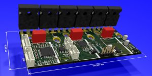
Serious FOCer (84V VESC 6 based controller)

shaman said:
Yes that's the one I've looked at to use. I've already mentioned that in this thread.

I agree that a 12 TO-247 is possible. It would just be a bit expensive. You're right that the energy output would be big for it's size. I may design one anyway.

Yes, it would be certainly powerfull. Maybe with TO-247 mounted under the main PCB like this https://obrazki.elektroda.pl/2050230600_1391595843.jpg to have minimal footprint and easy mount on heat sink with some screws, with the control logic and drivers on the upper side to limit distance between drivers and fets, with a bunch of caps and some copper bus bar (or thick copper wires to keep it cheap). What do you think ?
 
This sort of FET orientation is something I'm saving for a 30kW controller or higher. @galp is doing exactly this but with TO-220s as you already know. I intend to do a higher power controller design after I test these new FOCers. I'll look into using 150V TO-247s for the high-powered FOCer along with integrating the support for sin/cos encoders. I can do this now thanks to @marcos. Think of it as my pass at a "SEVCON killer". We'll see if I do any good.
 
shaman said:
Yes that's the one I've looked at to use. I've already mentioned that in this thread.

I agree that a 12 TO-247 is possible. It would just be a bit expensive. You're right that the energy output would be big for it's size. I may design one anyway.

The price is not skyrocket, with only about 5$ for ten quantity, it is 60$, certanily the biggest part of the esc but the fets chosen are important, and the thermal handling capability of 12 of these beasts on good heat sink would be unbeatable. The only real question is, does the DRV8353 able to drive them between 20 to 30kHz in any conditions without any problem ? if the answer is yes, this could be a very powerfull AND reliable ESC to power some high perf ebikes or to do some little motor bike conversion ;)
 
The DRV8353RS can only do 12 of these TO-247 FETs at a max of 20kHz for FOC. Higher switching frequencies is too much for the DRV with FETS of a gate charge this size. Higher power is better achieved with TO-220 FETs in parallel for this DRV. I can better do a 18 TO-220 FET controller than a 12 TO-247 FET controller with this particular DRV.

The DRV8353RS isn't meant for large power stages and one would most likely switch to independent gate drivers per H-bridge if going larger than what I'm already doing.
 
shaman said:
The DRV8353RS can only do 12 of these TO-247 FETs at a max of 20kHz for FOC. Higher switching frequencies is too much for the DRV with FETS of a gate charge this size. Higher power is better achieved with TO-220 FETs in parallel for this DRV. I can better do a 18 TO-220 FET controller than a 12 TO-247 FET controller with this particular DRV.

The DRV8353RS isn't meant for large power stages and one would most likely switch to independent gate drivers per H-bridge if going larger than what I'm already doing.

That make sense. what type of TO-220 do you plan to use ? for example, the IPP023N10N5 is pretty good, but seems to have the same gate charge than IRF100P219 and same kind of switching speed, so it should have the same limitation than IRF100P219 when driven by DRV8353RS (I could be totaly wrong as I'm no expert :) ) ? thx to take time for me !

Do you have an idea of when your design would be ready ?
 
The 100V TO-220 I am seeking to use is the NCEP01T18 by WUXI NCE Power Semiconductor. They're a manufacturer in China but they seem to have decent products. LCSC stocks some if their products but not all. I intend to contact them when I'm ready for production. If they don't turn out to work, then infineon will most likely be who I go with. Keep in mind this FET wouldn't be for a 18 FET version.

http://www.ncepower.com/Upload/SGT/NCEP01T18datasheet-11020580007.pdf

I don't have a formal schedule for my products. I'm doing them in my spare time for now. I'm currently trying to get the Beta testing launched for my Cheap FOCer so that's where most of my time is going right now. I'm hoping to have functional prototypes of these controllers by July or so. Of course funding helps speed up development
 
This is a very cool project and I've been looking for a way to try out different TO-247 mosfets in a motor control application. Do you think this board will be able to support 150A phase to test high power devices to the leg limits of the package?

Also, if I can help by alpha testing or helping with circuit layout, let me know. I do circuit and mechanical prototyping and design for embedded systems in my day job and play with high voltage/power in my spare time.
 
SRFirefox said:
Do you think this board will be able to support 150A phase to test high power devices to the leg limits of the package?

Maybe. It's all going to be about for how long it could do it. 30s? 30mS? Calculating something like this generally explodes into a massive cloud of variables, assumptions, and eventually only boils down to something just barely better than a guess. I prefer to extract this sort of data in real testing. I would guess that 150A could not be sustained continuously by 6 TO-247 FETs.

Thanks for the offer with testing. I'll be PMing people when it gets closer to that time.
 
Interested in this controller as well.
Won't that one be better alternative?
https://eu.mouser.com/ProductDetail/ON-Semiconductor-Fairchild/FDBL86062-F085?qs=sGAEpiMZZMshyDBzk1%2FWi%2FD7Em5shE8q2Wwbr9sX%252Bqck5TZDb7JrYQ%3D%3D
1.5mR, 124nC
 
Glad you are interested! See the discussion about SMD FETs earlier in this thread and my other thread about the Cheap FOCer controller. Conclusion was that they're not repair friendly and not ideal to heatsink..
 
View attachment 1

Side angled.JPG

Sorry for the lack of updates here. Been refining the layout and made a few changes

Changes:
  • Addition of JST PH connectors for all connections except the programming header.
  • Addition of film and ceramic capacitors at power stage for improved voltage oscillation/spike suppression
  • Changed current sense resistors to 2512 package.
  • Widened DC input and motor phase through hole pads to accommodate 10AWG cables.
  • Transitioned to SMD inductors instead of through hole
  • Improved DC/DC buck converter layout
  • Using through hole gate resistors on low-side FETs as a sort of “jumper” over high-current switch node.
 
There should be through hole version of these mosfets. At least similar specs could be used: https://www.onsemi.com/PowerSolutions/product.do?id=FDB1D7N10CL7

I think you should make power pads a much more wider and those chinese NCEP01T18, while being the worst in the list performance wise, could be also a pieces of crap
 
Andrewol said:
There should be through hole version of these mosfets.

The product page only advertises D2PAK-7/TO-263-7. No through hole packages

Andrewol said:
I think you should make power pads a much more wider

What do you mean by this?

Andrewol said:
NCEP01T18, while being the worst in the list performance wise, could be also a pieces of crap

The advertised specs of these are actually pretty good for 100V TO-220 MOSFETS and the price is great. Yes they could be garbage but I will being testing them before using or recommending them.
 
By power pads I mean P6-P8, GND pads on your board. They are only 1mm wide I believe
 
Clever use of through hole components as selective jumpers on a mostly SMD design. It looks very clean and well planned out!
I can't tell where the leads for the 560u caps go, or are those intended to be wrapped around the +/- battery leads? Also, I assume the NTC1 on the left side is meant to be lead out and placed against a MOSFET or the heat sink.
 
Thanks for the nice comments!

SRFirefox said:
I can't tell where the leads for the 560u caps go,

The leads are colocated with the leads of the film capacitors. I'm trying an experiment with doubling up the leads through the same pads due to space constraints. We'll see if it works. FYI ceramic caps are actually underneath the film caps.

SRFirefox said:
I assume the NTC1 on the left side is meant to be lead out and placed against a MOSFET or the heat sink.

This is correct. This is exactly what I did for my Cheap FOCer controller. I just don't have a good model for that.
 
Any update in verification?
Have you done any simulation with controller? I would like to try to build it this season if possible).
 
I submitted my design for review a couple of days ago. I haven't done any simulation since I don't have that capability. I will build a prototype and analyze that to find any issues.
 
You can use LTSpice program to simulate. It's free of charge. You can check power, temps, voltages, currents, oscillations, so on. It's almost impossible to design electronics without simulation if you are not highly experienced engeneer which will take a long way without simulation.
 
Can I model the MCU and its firmware with this? Can I model the PCB? I've used simulation software in the past for analog circuitry but not for anything as complicated as a whole motor controller. Maybe it's more advanced these days. Either way, I've had good luck leveraging the talent of engineers more experienced that I and then just analyzing a prototype.
 
As I know it's for simulating the circuit only. Perhaps there are more advanced solutions available, but im not familiar with such pro software.
Found powersimtech software for motor controllers. There is trial version available.
 
You can use LTSpice program to simulate. It's free of charge. You can check power, temps, voltages, currents, oscillations, so on. It's almost impossible to design electronics without simulation if you are not highly experienced engeneer which will take a long way without simulation.
You are asking for simulating something that can't be simulated. Parasitics are a critical part of a motor drive, they can break you powerstage and its just not practical to simulate. What is the parasitic inductance between the DC Link and the mosfet leg? That will determine the voltage overshoot and depends on how its laid out.

If you are looking for a bigger picture you can export the SVM output of a VESC and introduce it into LTspice to do some simulation of a VESC drive.
https://youtu.be/x6lPdI9OVQg?t=1806

That provides some validation support. I prefer to simulate the rest of the circuits that are not that much skewed by unknown parasitics, or just document the math behind a design decision.
 
Thank you @marcos. Yes I have learned the hard way that parasitics influenced by layout are a big deal. I learned that during the development of my Cheap FOCer controller.

@Andrewol I still appreciate you trying to offer help by suggesting simulation. It just may not be practical in this case. Besides, traditional prototyping is fun for me and I enjoy it!
 
Back
Top