
You are using an out of date browser. It may not display this or other websites correctly.
You should upgrade or use an alternative browser.
You should upgrade or use an alternative browser.
Super sized stand-up Scooter project. Build thread
- Thread starter Goped ESR750
- Start date
sk8norcal
1 MW
trying to picture what the finished scooter would look like... 8)


Goped ESR750
10 W
- Joined
- Sep 22, 2010
- Messages
- 86
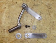
Been busy finishing the swing arm. This was all trial and error, and especially difficult to get the measurements right. I have changed the design again. Gone for a 12mm plate with a bush welded on the end. This looks far better.I need to make a brake mount for the calliper but apart from that is finished.
Frame should come together pretty quick now. The most of it was the rear swing arm. Motor mounts and battery boxes are a while away. Will be building these around a rolling frame, so have not even thought about how these will look yet.
Some pictures of progress.


Frame should come together pretty quick now. The most of it was the rear swing arm. Motor mounts and battery boxes are a while away. Will be building these around a rolling frame, so have not even thought about how these will look yet.
Some pictures of progress.
E-racer
1 kW
DAMN MAN! you now how to build a beast! This thing is turning out great! keep the pics coming.
999zip999
100 TW
Very nice I wish I could weld like that. Hot pic's.
Goped ESR750
10 W
- Joined
- Sep 22, 2010
- Messages
- 86
Here's a few more pictures. Got the frame parts laid out on the floor including motor. The bends are going to get cnc bent to this mock up, as the bender kinked the pipe. Definitely look like the odd one out against all the choppers in the workshop lol.


E-racer
1 kW
Nice I'm really liking this machine! Check out my build I've made some progress! http://endless-sphere.com/forums/viewtopic.php?f=28&t=35341&p=515258#p515258
motorino magnet
100 W
- Joined
- Nov 29, 2011
- Messages
- 188
you building with some incredible talent and skill...
watching ya thick E_Harley ride tadpole too
watching ya thick E_Harley ride tadpole too
E-racer
1 kW
OP post new pics!
Goped ESR750
10 W
- Joined
- Sep 22, 2010
- Messages
- 86
Ok, got some progress back on this project now.
Had waited for nearly 3 months for the tube to be bent. It was 50mm 3.5mm thickness I think, and the bends where getting closer to 90 degrees. As soon as got the tube back started working on the notch in the pipe to take the head tube. Not the easiest of task, took a short while but am happy with it.
Hopefully should be getting the thing in a jig tomorrow to square it all off and weld the head tube in place.
Here's a few picture of where I am at.
E-racer
1 kW
YESS! so excited to see this get updated. Keep-um coming!
Goped ESR750
10 W
- Joined
- Sep 22, 2010
- Messages
- 86
Been working on this again. Ended up making a make do jig out of wood. Seem to do the trick. Have a rolling frame now. There is a few gussets to be made to reinforce the frame, but other than that this is how it should look. Might shorten it a bit seems quite long but I have not mounted the motor yet which will take up some deck space. I locked the rear suspension in position at the moment. Have not made a tool to get the poly in yet. Frame is a bit big to get it a press now. Here is a few pictures of where I am at.


Goped ESR750
10 W
- Joined
- Sep 22, 2010
- Messages
- 86
Here is clip of front suspension.

Ykick
1 GW
Looking great, thanks for updates!
It is definitely "super sized" but overall proportions look good to my eye. I'm very curious how the front sus works? 'should eliminate dive under front braking, yes? That's a helpful thing with standup scooters with so little ground clearance to start with.
Cool build...
It is definitely "super sized" but overall proportions look good to my eye. I'm very curious how the front sus works? 'should eliminate dive under front braking, yes? That's a helpful thing with standup scooters with so little ground clearance to start with.
Cool build...
Goped ESR750
10 W
- Joined
- Sep 22, 2010
- Messages
- 86
Thanks Ykick. Not entirely sure of the technicals about the front suspension. I used this style because it was a single sided swing arm, where I am basing this on a GoPed I felt this would be best as they are supported single sided aswell.
Made and welded the gussets on today. Ground the weld of from the tube to the box and welded again as I wasn't happy with the penetration or look of the welds. Also will be grinded the weld of off the swing arm. This I will take to work to get welded as my set at home just didn't seem to put enough heat into the swing arm shaft.
Here is a few pictures of where I am at.
Goped ESR750
10 W
- Joined
- Sep 22, 2010
- Messages
- 86
Finally got to test the rear suspension. Was a difficult job to get the rods in there, and they have to come out before the frames powder coated, so should fun getting them back in again.
here's a few pics of progress plus a video of suspension moving.


here's a few pics of progress plus a video of suspension moving.
E-racer
1 kW
nicee! looks like it moves great! I really want to make one of these now. When does the motor go on!? and what is the drivetrain?
Goped ESR750
10 W
- Joined
- Sep 22, 2010
- Messages
- 86
Been busy on the drive side of the scooter. Looking at mounting the rear pulley and starting to make a motor mount.
i am going to mount the motor on a 10mm aluminium plate, which will then bolt to an adjustable steel motor mount welded to the frame.
Since the scooter is a single sided swing arm, the only way I am going to be able to mount the rear pulley is by drilling and tapping the wheel nuts, and mounted of off them.
the drive is going to be 50mm wide 8mm pitch HTD belt. The ratio is 1 to 4. The rear sprocket is 112 tooth which is a particularly large size sprocket. I am using a cast iron pulley as a representation, whilst an aluminium pulley is being made. As I want the send the cast iron pulley back I havnt machined it, so I have just place the pulley hub on top of the studs. However the studs will actually sit 30mm inside the hub bringing the pulley 30mm closer to the wheel. Leaving only 3mm clearance in the centre at it tightest point.
Few pictures of where I am at.
E-racer
1 kW
This is truly special. Keep um coming!
Oh my god. An eTek on a friggin' stand up scooter. And here are people telling me that i'm crazy for putting one on a bike. I'm not even done with my build and you already one-upped me :lol:
This is truly badass. I'm in awe and can't wait to see the final project.. rock on!!
This is truly badass. I'm in awe and can't wait to see the final project.. rock on!!
TopCat
100 W
My thoughts as well Nep -"An eTek on a friggin' stand up scooter".
That things going to go slicker than shit off a shiny shovel
Regards
Tom
That things going to go slicker than shit off a shiny shovel
Regards
Tom
Goped ESR750
10 W
- Joined
- Sep 22, 2010
- Messages
- 86
Thanks for all the comments. Glad my build is getting some interest.
Been working on making a hub for the rear wheel. I decided that a 50mm belt is not really a good idea. The cost to manufacture an aluminium pulley is too much. I have decided to go to chain instead.
The hub I made uses a phosphor bronze bush which is bolted onto the shaft of the rear wheel. A sleeve from the hub with a bearing inside is tightly fit over the bush centering the hub. The sprocket will be bored to match the 60mm recess on the other side of the rod. It is all assemble on precision spacer via the tapped heads of the wheel nuts.
I have yet to get the sprockets delivered will only need to bore the out to 60mm then drill the bolt holes. The sprocket will then centre itself on the hub which runs in line with the wheel bearings, as all three bearings are on the same shaft.
Few pictures of where I am at.
E-racer
1 kW
why not ditch the rear hydraulic brake and run the chain on the inside? does your controller have regen?
NVM just realized that is impossible. Looking great tho good luck getting it finished up! How much controller and what batts!?
NVM just realized that is impossible. Looking great tho good luck getting it finished up! How much controller and what batts!?
Goped ESR750
10 W
- Joined
- Sep 22, 2010
- Messages
- 86
Not decided on controller... But expect it will be 400amp Kelly. Batteries will be Lipo, turnigy. Using 8 series packs, in 2p8s configuration to give around 60v. Still working on the drive, got the hub and rear sprocket mounted. I am going to have to guide the chain either over or under the suspension knuckle as it looks like it is in the way. I am now working on making the steel motor mount which will weld to the frame and then the aluminium motor plate will bolt to it. Few pictures of where I am at.


Similar threads
- Replies
- 17
- Views
- 1,679
- Replies
- 1
- Views
- 958
- Replies
- 284
- Views
- 94,611
- Replies
- 10
- Views
- 1,367