speedy1984
100 W
- Joined
- Sep 28, 2018
- Messages
- 248
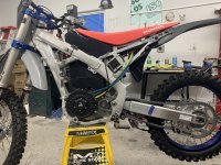
Looking good :thumb: Am i seeing things or have you chopped the centre section of the frame out?
You will need to read back in the thread, he extended it.by speedy1984 » Jan 08 2023 8:22am
Looking good :thumb: Am i seeing things or have you chopped the centre section of the frame out?
speedy1984 said:Looking good :thumb: Am i seeing things or have you chopped the centre section of the frame out?
rivvs said:speedy1984 said:Looking good :thumb: Am i seeing things or have you chopped the centre section of the frame out?
no on the shock mount on the 2017 and up honda is a lot lower than the previous generation. So there is way more space over the shock.
j bjork said:Looks good :thumb:
Do you plan to put steel spacers between the bracket and swingarm? (I see that you left some space there)
I think that can be a good idea, the alu gets a bit soft.
Is it the autput shaft from the bike you use and mount the sprocket on?
Will you be able to use it, or is it just a mockup ?
At first I wanted to use pouch cell but I could not find a good source for them.speedy1984 said:Im defo using pouch cells on my next build,there has to be a better way.Starting to look like a bike now :thumb:


This Display is very nice.Update on the build:
I finishing all the drawing for the battery busbar and sent them to a company on alibaba to get them made.
Also decided to change the bms. I will go with the ennoid bms because it will be able to comunicate with the vesc via canbus and also with the new display that I bought.
The display will show speed, range, amperage, temperature,fault and parts wear counter and will also show the information from the bms. So everything will communicate togheter. This will not be cheap but with the amount of money I have invested in this build I dont want everything to go up in flames like my previous build.
View attachment 330361View attachment 330362
I bought it on davega website. But you need vesc based controller for it to work.This Display is very nice.
How do I get it?I want to use it in my Dirt Bike Build as well.
Exactly the bms communicae to the controller via canbus and the display use uart to communicate with the controller.Does it have any voltage limitations? If it's designed for esk8, I would expect a limit of 16s or so.
Edit:
Looks like it only connects via rx/tx, so it doesn't read voltage directly, no limitations there probably
Thank you for the information. How is the 3shul controller?Have you been able to test it?I bought it on davega website. But you need vesc based controller for it to work.
I have tested it only with motor with no load since the bike is not finished yet.Thank you for the information. How is the 3shul controller?Have you been able to test it?