
casainho
10 GW
- Joined
- Feb 14, 2011
- Messages
- 6,045
This approach seems good because each ADC unit (10 bits) represents 0.156 amps, the best the system can measure. With the 8 bits variable we can store up to 40 amps. So, I would say we could read the 10 bits ADC value and just store on 8 bits variable:buba said:One approach would be to still keep the 8 bit value but convert it to ui8_battery_current_x6 or ui8_adc_battery_current. Then the operations and variable sizes of 8 bit would remain. Only difference is that we convert the 10 bit ADC value to 160 mA current steps during the ADC conversion. Not saying that is the best approach but am trying to convey that there are several ways of doing it and still maintaining speed and even simplifying code.
ui8_adc_battery_current = (uint8_t) ui16_adc_read_battery_current_10b();
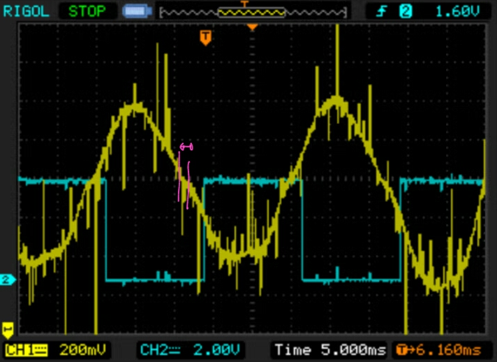
Then filtering is missing and this current measure on the shunt resistor should be VERY noisy, because the PWM motor phase currents goes over there. But the true is that I can't say how much filtering we need, I guess we would need to try and see.
We are filtering in 3 different types on our firmware:buba said:casainho said:2. Low pass filter of analog signals
This motor has wires with high peak currents and PWM high frequency, meaning the electric signals should be noisy.
On the analog signals measured by the ADC, the first 2 bits of the 10 bits are being discarded and this results in a fast way that filters the noisy analog signals.
To discard two bits and therefore reduce the resolution with a factor of 4 is one way of filtering the values. This will remove noise that is between the 625 mA steps. But on the other hand you loose the resolution. Could be possible to filter the value in the same way the other measurements are filtered. But without having seen the type of noise and the amplitude I can not say much. Just that I have never used a sensor without some form of filtering. And more often than not it has been software filters.
1. discarding the 2 first bits
2. average
3. slow time reading/ reduced frequency sampling
For the ui8_adc_battery_current we are using 1.
2 and 3 do not work because they are slow/make a delay and we need fast reaction (at least the way I see all this working).
2. and 3. are being used for reading torque sensor, throttle.
")