TSDZ2 EBike wireless standard (like Specialized Turbo Levo) - OpenSource

@ Casainho, I have completed the bootloader mods you requested and my testing indicates that is works well.
I have generated Pull Requests for both the bootloader and TSDZ2_wireless.
The way the bootloader now works:
You can DFU mode by:
1. entering ANT_ID of 0x99
2. pressing GPIO buttons after a board reset. This can be done either by a power cycle, an intentional reset in code, or as we discussed, the board will also reset when coming out of low power mode.
When a reset happens, the Bootloader will sense GPIO button pins on start up.
Currently, the PLUS__PIN on the remote and the board BUTTON_1 are sensed. If either of these buttons are pressed on entry, an adjustable timer starts which is currently set at 10s.
if the button is still pressed after 10s the board will enter DFU mode.
if the button is released before 10ss the bootloader will start the installed application immediately, effectively cancelling DFU mode

Please test and let me know if any other changes are needed. If OK, I will modify the documentation and make new videos.
 
rananna said:
Please test and let me know if any other changes are needed. If OK, I will modify the documentation and make new videos.
Thanks!!

I was testing and my board never enters in bootloader when I press the button at startup. I always see a very quick red LED turn on that seems the code actually works as you did but never detects my board button... maybe I am missing something, maybe any configuration about the board pin??
 
casainho said:
rananna said:
Please test and let me know if any other changes are needed. If OK, I will modify the documentation and make new videos.
Thanks!!

I was testing and my board never enters in bootloader when I press the button at startup. I always see a very quick red LED turn on that seems the code actually works as you did but never detects my board button... maybe I am missing something, maybe any configuration about the board pin??
In the pr note I mention the config gpio as pinreset option creating a problem that openocd erase doesn't fix. Anytime ithe option is compiled and used it will permanently set p18 to a reset pin and set it low so the button will not eork. Please compile and run this github repository and try again. It will clear the psel register that the config gpio as pinreset option sets
Here it is
https://github.com/rananna/pselreset

The bootloader will also recognize the plus pin on the remote. Does that work?
 
rananna said:
In the pr note I mention the config gpio as pinreset option creating a problem that openocd erase doesn't fix. Anytime ithe option is compiled and used it will permanently set p18 to a reset pin and set it low so the button will not eork. Please compile and run this github repository and try again. It will clear the psel register that the config gpio as pinreset option sets
Here it is
https://github.com/rananna/pselreset

The bootloader will also recognize the plus pin on the remote. Does that work?
Ok, I did flashed pselreset a few times but still with the same result. I even used the DEBUG ?= 1 on the Makefile and I were able to debug, the button press never puts the (nrf_gpio_pin_read(BUTTON_1) == 0) -- maybe it is my board issue??

I also installed latest github OpenOCD and with that I were able to execute nrf5 mass_erase, which should fully erase. But the button still do not work...

But I changed the code to test other pin and it worked!!

I don't have the remote with me so I can't test next days.
 
casainho said:
rananna said:
In the pr note I mention the config gpio as pinreset option creating a problem that openocd erase doesn't fix. Anytime ithe option is compiled and used it will permanently set p18 to a reset pin and set it low so the button will not eork. Please compile and run this github repository and try again. It will clear the psel register that the config gpio as pinreset option sets
Here it is
https://github.com/rananna/pselreset

The bootloader will also recognize the plus pin on the remote. Does that work?
Ok, I did flashed pselreset a few times but still with the same result. I even used the DEBUG ?= 1 on the Makefile and I were able to debug, the button press never puts the (nrf_gpio_pin_read(BUTTON_1) == 0) -- maybe it is my board issue??

I also installed latest github OpenOCD and with that I were able to execute nrf5 mass_erase, which should fully erase. But the button still do not work...

But I changed the code to test other pin and it worked!!

I don't have the remote with me so I can't test next days.
I'm sorry you are having so much trouble with the board button! You have certainly done everything possible to get it working.
I have 3 boards, and all are working, so maybe it is a faulty board.
Btw, did you notice if you release the pin it immediately loads the app?
I was pleased that the event nterrupt worked with a simple nrf_ delay timer as it greatly simplifies the code.
Is the logic implemented correctly for your needs?
 
rananna said:
I'm sorry you are having so much trouble with the board button! You have certainly done everything possible to get it working.
I have 3 boards, and all are working, so maybe it is a faulty board.
Btw, did you notice if you release the pin it immediately loads the app?
I was pleased that the event nterrupt worked with a simple nrf_ delay timer as it greatly simplifies the code.
Is the logic implemented correctly for your needs?
Ok, I will forget to test this on this board and consider it works.

I was not able to fully test, I need more time.

I am not sure it is ok for the remote, as the delay, I am sure the remote will always do it at boot and I am not sure that delay is low power. We need to optimize the remote firmware for low power and then the bootloader for low power.

I know that app_timers are low power, they use RTC to count the delay time and the processor can be halted in low power.

And this reset seems avoidable, would be better to set a flag that could after set the dfu_enter variable.

Code:
            nrf_delay_ms(BUTTON_DFU_WAIT);                //wait 10 seconds before going to dfu mode
            nrf_power_gpregret_set(BOOTLOADER_DFU_START); //set the dfu register
            nrf_delay_ms(1000);                           //wait for write to complete
            do_reset();                                   //reset and go to dfu mode
 
casainho said:
I am not sure it is ok for the remote, as the delay, I am sure the remote will always do it at boot and I am not sure that delay is low power. We need to optimize the remote firmware for low power and then the bootloader for low power.
Nrf_delay is probably not low power.
However, to be in the bootloader, the remote is already woken up by a button press from low power mode. As this code is only used when the user is requesting a dfu, I don't think power consumption is relevant. Normal operation of the bootloader when dfu is not requested will bypass this code and simply loads the remote app quickly and with low power.
casainho said:
And this reset seems avoidable, would be better to set a flag that could after set the dfu_enter variable.

Code:
            nrf_delay_ms(BUTTON_DFU_WAIT);                //wait 10 seconds before going to dfu mode
            nrf_power_gpregret_set(BOOTLOADER_DFU_START); //set the dfu register
            nrf_delay_ms(1000);                           //wait for write to complete
            do_reset();                                   //reset and go to dfu mode
Yes, you are probably right. I will look into it.
 
I found a really good blog post on optimizing power consumption:

https://devzone.nordicsemi.com/nordic/nordic-blog/b/blog/posts/optimizing-power-on-nrf52-designs
Here are my thoughts:

As the 52840 chip is spending almost 100% of its time NOT executing bootloader dfu code power consumption so imo that code is unimportant.
In dfu mode, the extra 10s of very slightly higher pwr consumption for a software nrf_delay can be ignored.
The led flashing in dfu mode consumes much more power

The remote is also spending almost 100% of its time in the idle loop.(buttons are not pressed much of the time during a run, and the remote sits idle when you are not riding) also, Bluetooth is off, so there is no power drawn from the radio.
It seems we just need to be sure that the cpu in in the SYSTEM_OFF state by using power_manage() in the idle loop.
This conclusion is supported by this article also:
https://medium.com/jumperiot/power-optimization-from-3-to-7-months-on-a-single-charge-56de0c30f062
 
@Casainho I would be willing to undertake a project to minimize the power consumption of the wireless remote firmware.
Let me know if you are interested in this.
 
casainho said:
And this reset seems avoidable, would be better to set a flag that could after set the dfu_enter variable.

Code:
            nrf_delay_ms(BUTTON_DFU_WAIT);                //wait 10 seconds before going to dfu mode
            nrf_power_gpregret_set(BOOTLOADER_DFU_START); //set the dfu register
            nrf_delay_ms(1000);                           //wait for write to complete
            do_reset();                                   //reset and go to dfu mode

I did look into it and the reset is needed to clear the GPIO interrupt for the button release before entering dfu mode
otherwise, the button up event is triggered during dfu mode which causes problems.
I could have turned off this gpio event in code, but the reset is a much simpler solution.
 
casainho said:
I am not sure it is ok for the remote, as the delay, I am sure the remote will always do it at boot and I am not sure that delay is low power

I forgot to mention this, but the delay ONLY happens when a button is pressed upon bootloader entry
It will not delay at all if a normal boot happens with no button pressed
see:
Code:
if ((nrf_gpio_pin_read(PLUS__PIN) == 0) || (nrf_gpio_pin_read(BUTTON_1) == 0)) // button pressed
        {
            //start a timeout for DFU mode
            // if the button is released before timeout, button_released() is called and the board resets
            nrf_delay_ms(BUTTON_DFU_WAIT);                //wait 10 seconds before going to dfu mode
            nrf_power_gpregret_set(BOOTLOADER_DFU_START); //set the dfu register
            nrf_delay_ms(1000);                           //wait for write to complete
            do_reset();                                   //reset and go to dfu mode
        }

/code]
 
rananna said:
casainho said:
I am not sure it is ok for the remote, as the delay, I am sure the remote will always do it at boot and I am not sure that delay is low power

I forgot to mention this, but the delay ONLY happens when a button is pressed upon bootloader entry
It will not delay at all if a normal boot happens with no button pressed
see:
Code:
if ((nrf_gpio_pin_read(PLUS__PIN) == 0) || (nrf_gpio_pin_read(BUTTON_1) == 0)) // button pressed
        {
            //start a timeout for DFU mode
            // if the button is released before timeout, button_released() is called and the board resets
            nrf_delay_ms(BUTTON_DFU_WAIT);                //wait 10 seconds before going to dfu mode
            nrf_power_gpregret_set(BOOTLOADER_DFU_START); //set the dfu register
            nrf_delay_ms(1000);                           //wait for write to complete
            do_reset();                                   //reset and go to dfu mode
        }
When we wakeup the remote by clicking in the button, we may keep the button pressed like 500ms, so, that PLUS__PIN will be pressed and will enter that if and will execute that nrf_delay_ms(BUTTON_DFU_WAIT);, I am pretty sure it is not low power as for that the code would need to call the nrf_pwr_mgmt_run();.

Maybe you should now focus on try to make, again, the remote power efficient. Then, go back to bootloader and apply what you learned.

I did that and tested on 27 August and you can see here the commit / code at that time: https://github.com/OpenSource-EBike-firmware/ebike_wireless_remote/blob/c2134ad3a38b0d638346d5bb54de03d51fd28957/firmware/main.c

The main loop was only this:
Note that I used the nrf_gpio_pin_xxx(10); to change a pin so I could see on the oscilloscope when the processor was running or not, I did did wakeup with a pin press or when the ANT did make the processor run.

Code:
  for (;;)
  {
    // enter System On sleep mode and manage extra features if they are enable
    nrf_pwr_mgmt_run();

    // // for debug only
    // static bool pin_state = 0;
    // pin_state = !pin_state;
    // if (pin_state)
    //   nrf_gpio_pin_clear(10);
    // else
    //   nrf_gpio_pin_set(10);
  }

And now after your changes, it is this:

Code:
  while (1)
  {
    //user has not made an ant ID change in the last 10 minutes after long press of PLUS button
    if (ui32_seconds_since_startup > 600 && enable_bluetooth)
    {
      ui32_seconds_since_startup = 0; // turn off bluetooth after 10 min if left on

      eeprom_write_variables(old_ant_device_id, 0); // disable bluetooth and restart
    }
    // main timer calls main_timer_timeout every 10ms
    // check every second
    if (main_ticks % (1000 / MSEC_PER_TICK) == 0)
    {
      // first see if there was a change to the ANT ID, if so, store in flash and turn the bluetooth on restart
      if (new_ant_device_id != old_ant_device_id)
      {
        old_ant_device_id = new_ant_device_id;
        eeprom_write_variables(old_ant_device_id, 0); // DISABLE BLUETOOTH on restart
      }
      // bluetooth needs to be turned on by long press of the PLUS button
      if (turn_bluetooth_on)
        eeprom_write_variables(old_ant_device_id, 1); // Enable BLUETOOTH on restart
      if (turn_bluetooth_off)
        eeprom_write_variables(old_ant_device_id, 0); // Disable BLUETOOTH on restart
    }
  }
 
casainho said:
When we wakeup the remote by clicking in the button, we may keep the button pressed like 500ms, so, that PLUS__PIN will be pressed and will enter that if and will execute that nrf_delay_ms(BUTTON_DFU_WAIT);, I am pretty sure it is not low power as for that the code would need to call the nrf_pwr_mgmt_run();.
This is true, but don't forget that the button release will immediately cancel the nrf_delay_ms and exit the bootloader, so the higher pwr consumption is only for a few ms.

casainho said:
Maybe you should now focus on try to make, again, the remote power efficient. Then, go back to bootloader and apply what you learned.
As I mentioned in my previous post I would be certainly willing to do this.
I will start investigating ways to minimize pwr consumption with a coin cell battery. Thanks for the code tips.
 
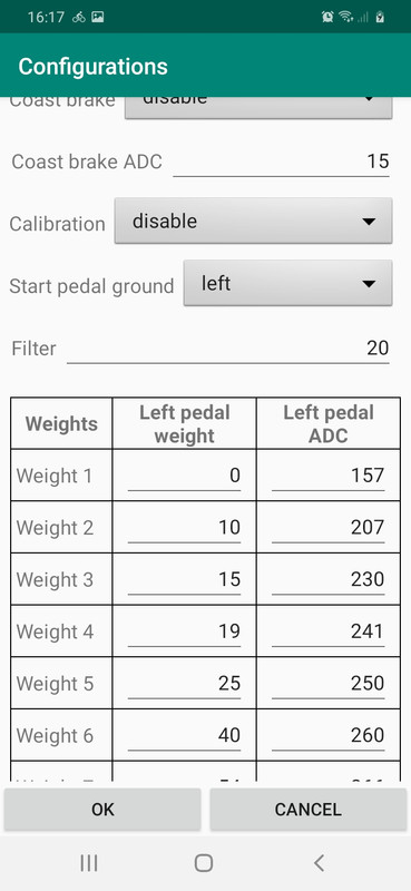
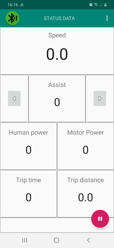
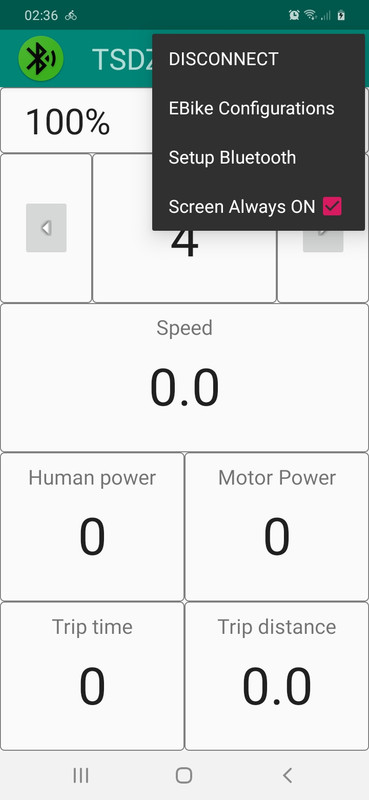
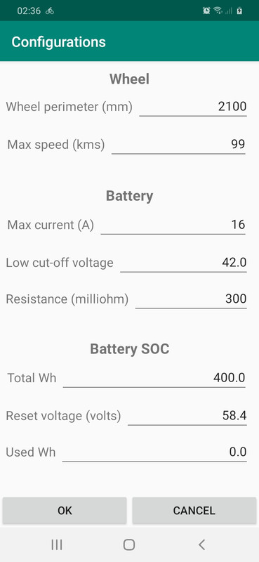
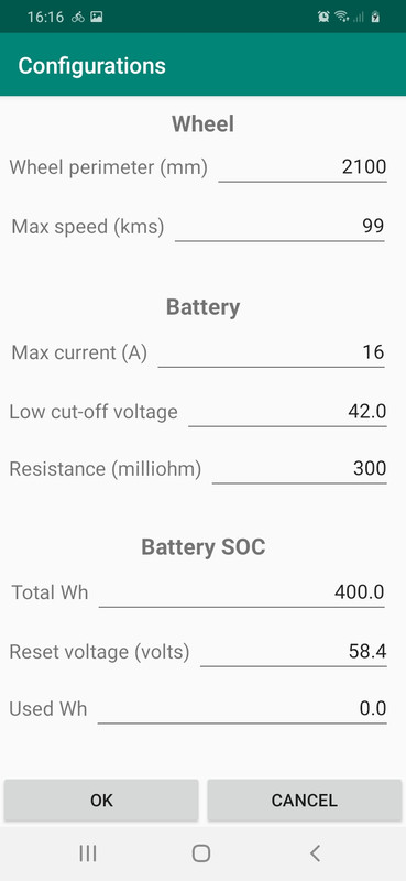
This is the current state of the mobile app:
- configurations are fully implemented (on Android and firmware)
- main screen is fully implemented (needs implementation on firmware side)

Since there will be some holidays on December, I hope to have a working version on my ebike at begin of January and make a public release. The bootloader firmware and wireless remote firmware, are being worked by @rananna and others with collaborations and discussions happening on github.

2020-11-29-16-16-39.jpg


2020-11-29-16-17-02.jpg


2020-11-29-16-16-25.jpg
 
Hi! What a luck I found my way to this part of the internet and spotted this thread/forum. You can publish this thread as ebook, it will have for sure success – lots of knowledge and dedication there! 😊 As I recently thought for myself: “Hmm, lets build some smart ANT/BT enabled remote for bike lights, finally utilise those Nordic boards in my drawer, and learn something in the process”, it is great I am aware of your project now.

I have several propositions for you:

- I am author of mentioned Ebike Field Garmin app and rider of Turbo Levo.

I saw your mentions that my current ebike apps doesn’t fully fit your needs. Tell me exactly what you are missing, and I might try to incorporate it to the apps. That way, you will not need to cover another technically different part of your project. I only can’t promise publishing source codes under GNU for several reasons – not sure how big problem it is for you.

Garmin Connect IQ apps are either standalone application shown among other activity apps within the device or datafields to be added to already existing activity app. Both variants have their own advantages/disadvantages. Datafields, like mentioned Ebike Field can’t have any user input, so it is not possible to control assist level thru it. On another hand, standalone apps like Ebike Diagnostics must completely replace activity app and must implement all features like activity recording on its own and some native activity apps features cannot be replicated at all.

I am also founder of WearSoft which develop Connect IQ solutions for other commercial partners, so I am well aware of Garmin and Connect IQ specifics.

- I am member of Locus Map team

Locus Map (FREE/PRO) is advanced outdoor navigation Android application which incorporates ability to connect BT/ANT sensors, customised dashboard on top of maps, track recording and literally hundreds of other features. Lots of cyclist are using our app on their handlebars as bike computer with navigation capability. The app can also connect to Garmin and other wearables. For next year we are preparing some Ebike specific features. They will for sure not go way of ability to do heavy configurations of specific bikes, but rather being able to utilise data from it and show them on screen with other activity / navigation info.

I am mentioning this because I believe I understand scope of your project and this might be way to extend it to be even smarter (or for those who don’t want to buy expensive Garmin EDGE computers). If you will find the app interesting, don’t hesitate to tell me for our considerations your ideas for integration with your project!

- I have similar project on my head

But because I already have original remote on my bike for controlling assist modes, my primary scope is different – to use it for controlling bike lights (on handlebar AND on helmet) and be able to have some user configurable presets for both (or even with back light). Secondary objective is ANT+ CONTROL to ability to control Garmin EDGE or Locus Map.

Here, I don’t know yet how can I help you. This is really personal hobby project with limited time budget for me at this stage, and you are much ahead now. (I even didn’t find good candidate for wireless headlamp which suits my needs.)

But as I will require next to BT/ANT to incorporate also wired controlling (for handlebar mounted gaciron lights) and I hate bulky remotes, I really like already mentioned idea of not integrating Nordic board directly under buttons but ideally to the different box on short cable to attach it somewhere near the center of handlebars or to stem. I already ordered VLCD5 remote, so looking forward to play with it. Will I finally vindicate purchase of 3D printer? 😊

Happy DIYing! :bigthumb:
 
JanCapek said:
- I am author of mentioned Ebike Field Garmin app and rider of Turbo Levo.

I saw your mentions that my current ebike apps doesn’t fully fit your needs. Tell me exactly what you are missing, and I might try to incorporate it to the apps. That way, you will not need to cover another technically different part of your project. I only can’t promise publishing source codes under GNU for several reasons – not sure how big problem it is for you.
My time is very limited and so I prefer to collaborate only on OpenSource projects otherwise it will be like my daily job and someone will have to pay me.
Alone, I would not be able to make this awesome projects, there are a lot of working of others developers like on the wireless remote and bootloader, @rananna and others are doing a great job.

JanCapek said:
Garmin Connect IQ apps are either standalone application shown among other activity apps within the device or datafields to be added to already existing activity app. Both variants have their own advantages/disadvantages. Datafields, like mentioned Ebike Field can’t have any user input, so it is not possible to control assist level thru it. On another hand, standalone apps like Ebike Diagnostics must completely replace activity app and must implement all features like activity recording on its own and some native activity apps features cannot be replicated at all.

I am also founder of WearSoft which develop Connect IQ solutions for other commercial partners, so I am well aware of Garmin and Connect IQ specifics.
Very limited. There are many things that annoy me, like I have on expensive Fenix 6X but I can only use 2 CIQ fields...
Anyway, we will do the best possible.

JanCapek said:
- I am member of Locus Map team

Locus Map (FREE/PRO) is advanced outdoor navigation Android application which incorporates ability to connect BT/ANT sensors, customised dashboard on top of maps, track recording and literally hundreds of other features. Lots of cyclist are using our app on their handlebars as bike computer with navigation capability. The app can also connect to Garmin and other wearables. For next year we are preparing some Ebike specific features. They will for sure not go way of ability to do heavy configurations of specific bikes, but rather being able to utilise data from it and show them on screen with other activity / navigation info.

I am mentioning this because I believe I understand scope of your project and this might be way to extend it to be even smarter (or for those who don’t want to buy expensive Garmin EDGE computers). If you will find the app interesting, don’t hesitate to tell me for our considerations your ideas for integration with your project!
That makes sense of integrate with other sensors and that is why EBike wireless standard is important to have on TSDZ2 motor, that will open a lot of possibilities!!

JanCapek said:
- I have similar project on my head as noted at the begining

But as I already have original remote on my bike for controlling assist modes, my primary scope is different – to use it for controlling bike lights (on handlebar AND on helmet) and be able to have some user configurable presets for both (or even with back light). Secondary objective is ANT+ CONTROL to ability to control Garmin EDGE or Locus Map.

Here, I don’t know yet how can I help you. This is really personal hobby project with limited time budget for me at this stage, and you are much ahead now. (I even didn’t find good candidate for wireless headlamp which suits my needs.)

But as I will require next to BT/ANT to incorporate also wired controlling (for handlebar mounted gaciron lights) and I hate bulky remotes, I really like already mentioned idea of not integrating Nordic board directly under buttons but ideally to the different box on short cable to attach it somewhere near the center of handlebars or to stem. I already ordered VLCD5 remote, so looking forward to play with it. Will I finally vindicate purchase of 3D printer? 😊

Happy DIYing! :bigthumb:
That is the beauty of OpenSource, you don´t need to start from the scratch your project for your wireless remote and you will not be alone, you will be able interact with other developers, learn and share knowledge :)
 
With the Iphone App, wouldn't it be quicker and easier to integrate BLEVO, its very good but limited to the Specialized bikes. Pity we hadn't gone down the route of simply mimicing the Specialized data fields as we could have then used all Specialized Apps :D

Looking foward to using it guys, now anybody got any spare boards ?
 
Waynemarlow said:
With the Iphone App, wouldn't it be quicker and easier to integrate BLEVO, its very good but limited to the Specialized bikes. Pity we hadn't gone down the route of simply mimicing the Specialized data fields as we could have then used all Specialized Apps :D
The idea is to use standards, since they exist.

Waynemarlow said:
Looking foward to using it guys, now anybody got any spare boards ?
All the boards are available for you to buy from many sources on EBay, Aliexpress, etc.
 
DEVELOPER HELP REQUESTED

The new Bluetooth wireless boot loader I added for both the wireless remote and the motor control firmware is working well, so I decided to look into the process a user would use to get started on the project with a brand-new makerdiary NRF52840 dongle.

I envision the process that a new user would use to get started to be:

1. Purchase the boards needed for the remote control and motor controller. (btw, wrt the previous post, check out Amazon prime for fast delivery and a low cost. ie, see: https://www.amazon.ca/GeeekPi-nRF52840-Micro-Dev-Dongle/dp/B07MJ12XLG)

2. Plug the board into a USB port on a computer and program the new boot loader

3. Wirelessly upload the firmware required for both the remote control and motor controller using the new bootloader

Simple , right? All we have to do is to replace the existing bootloader with the new one via USB and we are good to go.
This process has the significant advantage of avoiding the need for a new user to learn SWD programming with the ST link and the need for soldering programming connections.

Unfortunately, this simple process is proven very difficult to implement in practice
The reason for this is the UF2 bootloader that comes with the makerdiary board is signed privately, and cannot be replaced with a new bootloader without the private key information which is not available.

I did try to update the boot loader by creating a UF2 image and copying to the flash drive , but due to the signing protection this failed. I also tried using both ADAFRUIT-NRFUTIL and NRFUTIL for programming which also failed.

However, maker diary also offers the option of replacing this bootloader with open bootloader.
see: 'Change to Open Bootloader from UF2 Bootloader' here:
https://github.com/makerdiary/nrf52840-mdk-usb-dongle/tree/master/firmware/open_bootloader

Open bootloader does opens up the option of using the NRF CONNECT app for programming which makes uploading the new bootloader even simpler. So, I followed their instructions and loaded open bootloader, only to find out that this bootloader is also signed! No attempts to program were successful using NRF CONNECT, nrfutil or adafruit-nrfutil.

I contacted Nordic, and they refused to distribute the private key for open bootloader.

I have just started looking at trying to modify the bootloader code to programmatically overwrite the flash location (E0000) of the makerdiary , but so far, the signing protection of the existing bootloader is preventing an overwrite.

This has proven very frustrating for me .
Does anybody have any ideas on how we can use USB to replace the makerdiary bootloader with the new one?
It would greatly simplify the startup process for new users.
 
rananna said:
This has proven very frustrating for me .
Does anybody have any ideas on how we can use USB to replace the makerdiary bootloader with the new one?
It would greatly simplify the startup process for new users.
Good work!!

If the original bootloader is signed, then I would forget this option. Would be great if users would not need to solder the STLinkV2, but, there is also no big issue if they need to solder it. They will need to solder other wires and they will also need anyway a STLinkV2 to program the motor firmware.

Note about developments: the Android app now controls the assist level and I will continue to make all the periodic variables available on probably 3 main screens (similar idea like on 860C display main screens).

@rananna, if you can make a bootloader and remote stable versions, would be great!! because the mobile app may be finished in 1 or 2 weeks. Then we can make a public release of all this, and we will also need to make a good documentation :)
 
OK will do.
Please accept the last PR for the remote, and I will build the release version around that.
I will prepare user docs for both the bootloader and remote also.
 
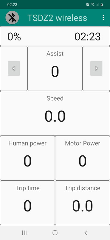
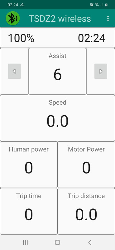
This is the current state of the mobile app.

I am following the same layout as on 860C display. For now, there is only one main page with that 5 fields as shown on the next screenshots. I already have long press detection on each field and I plan to show a list of the possible variables, so user will be able to customize which variables will want to see.

I also want to add the battery icon and with the current SOC numeric value inside, as seen on top left.

Then I will stop developing the mobile app and I will focus on the firmware side. Finally install on my ebike and then make a public release :)

2020-12-06-02-23-56.jpg
2020-12-06-02-24-15.jpg


2020-12-06-02-36-42.jpg
2020-12-06-02-36-59.jpg
 
Beautiful!
Does this app work connected to the SW102 Bluetooth only?
 
Nfer said:
Beautiful!
Does this app work connected to the SW102 Bluetooth only?
Only if someone will develop it. I am developing for the wireless board.
 
@casainho,

I have been investigating battery options for the remote control when I came across the Adafruit nrf52840 express.
See: https://learn.adafruit.com/adafruit-itsybitsy-nrf52840-express
This board has the significant advantage of including a USB charging port for a 3.7V backpack battery for long life between recharges
see: https://www.adafruit.com/product/2124
Otherwise it is about the same size as the makerdiary board.
This might help simplify packaging, as we could perhaps design a 3d printed enclosure that would expose both the led and USB charging port to the user while allowing for brake connections to the enclosure.
It is also a very inexpensive board like the makerdiary.
Downloads + schematic:
https://learn.adafruit.com/adafruit-itsybitsy-nrf52840-express/downloads.

3d design attempts:
http://cults3d.com/en/3d-model/tool/itsybitsy-case-m0-m4-and-nrf52840-adafruit

https://www.thingiverse.com/thing:3460550

https://learn.adafruit.com/led-trampoline/3d-printing


Thoughts?
 
Back
Top